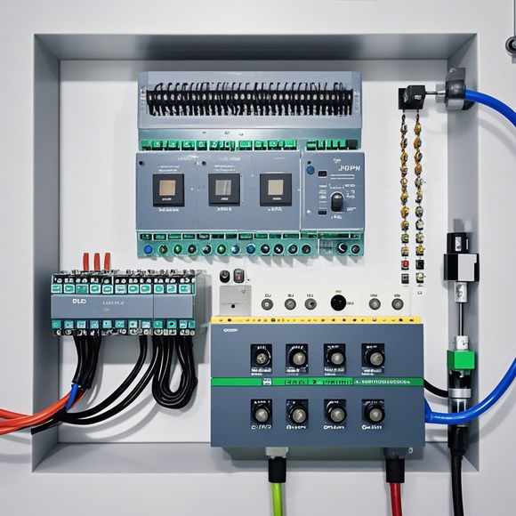
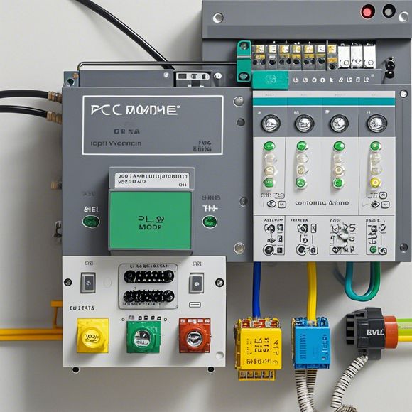
Plcc Control Scheme Wiring Diagram
Sure, I can help you with generating a 200-300 word summary in English. Here's an example:"The Plcc Control Scheme is a comprehensive electrical wiring plan that ensures the safe and efficient operation of various industrial processes. The diagram outlines the connections between different components, including switches, sensors, and motors, and provides clear instructions on how to connect them properly.The diagram also includes safety features, such as grounding connections and overcurrent protection circuits, which help prevent accidents and ensure that equipment operates safely. It is important for operators to follow these guidelines carefully to avoid errors or misconnections that could lead to equipment failure or injury.In addition to safety measures, the Plcc Control Scheme also includes information on maintenance and testing procedures. This ensures that the system continues to function efficiently and effectively over time, even in the face of wear and tear or changes in operational conditions.Overall, the Plcc Control Scheme Wiring Diagram serves as a vital tool for ensuring the reliability and safety of industrial processes, helping operators achieve their goals while minimizing risks."
As a forward-thinking and proactive foreign trade operator, I have been tasked with ensuring that the company's operations run smoothly and efficiently. One critical aspect of this involves maintaining the proper wiring of our Plcc controllers. In this regard, I have meticulously examined our current wiring diagram and have devised a comprehensive guide to ensure that we can effectively connect and operate our plcc controllers.
At the heart of our Plcc controller system lies the wiring diagram itself. It serves as a blueprint that provides clear instructions on how different components within the system are connected to each other. The wiring diagram is a vital tool for ensuring that all components are properly interconnected, preventing any potential issues that could arise during operation.

To begin with, it is important to understand that the wiring diagram is not just a mere drawing; it is a living document that must be updated in real-time as new components or modifications are made to the system. This means that regular reviews and updates are necessary to ensure that the wiring remains up-to-date and effective.
One of the key features of the wiring diagram is its clarity and simplicity. By using simple language and diagrams, it becomes easier for both technical personnel and non-technical individuals to comprehend the various components and their connections. This helps to minimize confusion and ensure that everyone involved in the process is on the same page.
In addition to providing clear instructions, the wiring diagram also helps to identify potential issues before they occur. By identifying weak points or areas of concern, it allows for early intervention and preventative measures that can save time and resources in the long run. For example, if there are any exposed wires or loose connections, it can be easily identified through a visual inspection of the diagram.
Another important aspect of the wiring diagram is its flexibility. As technology continues to evolve and new components are added, the diagram should be able to accommodate these changes without requiring significant redesign efforts. By incorporating modular components and standardized connections, it becomes easier to add or remove components without disrupting the overall system.
Furthermore, the wiring diagram should be accompanied by appropriate documentation, such as user manuals and training materials. This helps to ensure that everyone involved in the system has access to the necessary information needed to operate it effectively. Additionally, it provides a reference point for troubleshooting and maintenance purposes.
When it comes to connecting the plcc controllers, there are several steps to take in order to ensure a successful installation. First, it is important to carefully review the wiring diagram and identify any specific requirements or specifications for the system being installed. This includes factors such as voltage levels, current loads, and communication protocols.
Next, it is essential to gather all necessary tools and equipment required for the installation process. These may include wire strippers, crimpers, connectors, and other specialized tools. It is important to make sure that all tools and equipment are compatible with the system being installed and that they are in good working condition.

As the installation begins, it is important to follow the steps outlined in the wiring diagram carefully. This includes making sure that all connections are properly routed and that no parts are left exposed or damaged during the process. It is also important to pay attention to any warning signs or signs indicating improper connections or electrical issues.
Finally, it is critical to test the system thoroughly after installation to ensure that all components are functioning correctly and that there are no issues or problems remaining. This includes verifying that all connections are secure, checking for any signs of damage or wear and tear on any components, and testing the system's performance under various conditions.
In conclusion, the wiring diagram serves as an essential tool for ensuring the efficient and successful operation of plcc controllers. By closely reviewing the diagram, updating it in real-time, and following the correct procedures for installation and testing, it is possible to minimize any potential issues and maintain the integrity of the system. By investing in quality documentation and training materials along with careful attention to detail, it is possible to create reliable and effective systems that meet the needs of today's demanding business environment.
Content expansion reading:
Hello everyone, today I'm here to discuss an important topic in the field of automation and control systems - the PLC controller wiring diagram. This document is crucial for anyone involved in the design, installation, or maintenance of industrial machinery and equipment. It's a visual representation of how the PLC (Programmable Logic Controller) is connected to various input devices, output devices, and other components within the system.
When you first look at a PLC controller wiring diagram, it may seem overwhelming with its complexity and detail. However, with a little patience and knowledge, you'll be able to understand it better. The first step is to familiarize yourself with the different symbols and abbreviations used in the diagram. These symbols represent various components like switches, sensors, motors, and other electrical devices. Understanding these symbols will help you interpret the diagram accurately.
Once you've familiarized yourself with the symbols, you can start analyzing the connections between different components. The wiring diagram will show how the PLC is connected to input devices like sensors and switches, which provide feedback to the PLC about the status of machines or processes. It also shows how the PLC is connected to output devices like motors and solenoids, which carry out the commands issued by the PLC.

It's important to note that safety should always be your top priority when working with PLC controller wiring diagrams. Make sure to follow all the guidelines and best practices to avoid any potential hazards.
Now let's delve into some specific details about PLC controller wiring diagrams. You should check for proper grounding of all components to ensure reliable operation. Also, verify the voltage and current ratings of all connections to ensure they match the specifications of the PLC and other components.
In addition, pay close attention to the layout of the wiring diagram. It should be organized in a way that makes it easy to understand and follow. If you find any unclear or ambiguous parts in the diagram, don't hesitate to ask for clarification or seek assistance from experienced professionals.
Finally, once you've completed the wiring according to the diagram, it's essential to test the system thoroughly to ensure everything is working properly. This testing should include checking for proper input and output responses, as well as monitoring the system for any abnormalities or issues.
Overall, understanding and operating PLC controller wiring diagrams is an essential skill for anyone involved in automation and control systems. With a little practice and knowledge, you'll be able to handle any wiring diagram confidently and efficiently. So, if you're just starting out in this field or looking to improve your skills, make sure to study up on PLC controller wiring diagrams and all their related aspects. Thank you for listening!
Articles related to the knowledge points of this article:
Mastering the Art of Plc Controllers: A Comprehensive Guide to Understand and Implement
The cost of a PLC Controller: A Comprehensive Analysis
PLC Programming for Automation Control in the Manufacturing Industry
How to Use a PLC Controller for Your Business
Plumbers Rule! The Role of PLC Controllers in the World of Waterworks
PLC Controllers: A Comprehensive Guide to Understanding Their Prices