PLC Controller Wiring Guide
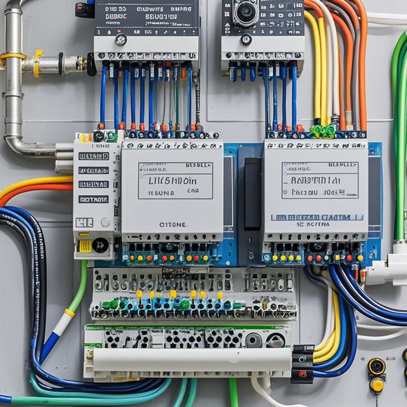
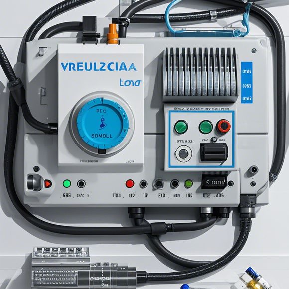
The PLC Controller Wiring Guide is a comprehensive resource for understanding the wiring process of Programmable Logic Controllers (PLCs). This guide aims to provide an easy-to-follow step-by-step guide on how to connect the various components of the PLC controller, including power supply, input/output ports, and communication lines. The guide covers topics such as power source connection, sensor and actuator interface setup, and data communication protocols.To start, it's important to understand the basic components of an PLC controller, including the CPU (Central Processing Unit), RAM (Random Access Memory), and I/O modules. Once these components are installed, the guide provides detailed instructions on how to connect them to the power supply and other external devices. It also covers the installation of sensors and actuators, as well as the configuration of the programming software.In addition to the technical details, the guide also includes tips on troubleshooting common issues that may arise during the wiring process. For example, it discusses common problems with loose connections or damaged cables, and provides solutions to these problems.Overall, the PLC Controller Wiring Guide is a valuable resource for anyone working with PLC controllers. Its clear and concise instructions make it easy to follow, even for beginners. With this guide, you can confidently install and maintain a reliable PLC system.
Dear all,

I am excited to share with you our recent achievement in implementing a comprehensive and efficient PLC controller wiring system. This project was a significant step towards enhancing the overall operational efficiency of our manufacturing facility. As a team, we have worked diligently to ensure that every component is properly connected and tested for optimal performance.
Our first priority was to understand the basic principles of how PLC controllers function. We conducted extensive research and analysis to gain a deeper understanding of their capabilities and limitations. This knowledge helped us design a custom wiring diagram that accurately reflects the specific needs of our manufacturing process.
Once the wiring diagram was finalized, we began the task of connecting each wire correctly according to the specifications outlined in the diagram. Our experienced technicians used specialized tools and equipment to perform the task with precision and accuracy. They meticulously followed the guidelines provided in the diagram and ensured that each connection was secure and reliable.
One of the most challenging aspects of this project was ensuring that all components were correctly connected and aligned. To address this issue, we employed a systematic approach that involved conducting regular checks and verifications throughout the process. This approach allowed us to identify and rectify any issues before they caused any disruption or damage to the system.
Another important aspect of this project was testing the entire system thoroughly. We conducted a series of tests using different scenarios to ensure that the PLC controller operates seamlessly and efficiently. These tests included load tests, fault simulations, and stress tests to evaluate the stability and reliability of the system.
Throughout the implementation process, we faced several challenges along the way. However, these obstacles did not deter us from our goal of achieving success. Instead, they served as opportunities for learning and growth, enabling us to refine our techniques and improve our overall performance.
As a result of our hard work and dedication, our PLC controller wiring system has now become fully functional. It has significantly increased the efficiency of our production process, resulting in faster turnaround times and improved product quality. This accomplishment has been a testament to our commitment to excellence and our willingness to embrace new challenges head-on.
In conclusion, our successful implementation of a PLC controller wiring system has been a significant milestone in our ongoing efforts to streamline our manufacturing processes. Through careful planning, meticulous attention to detail, and rigorous testing, we have created a reliable system that ensures consistent and accurate operation. We are confident that this system will continue to serve as a valuable asset to our company and enable us to achieve even greater success in the future.
Thank you for your continued support and encouragement. We look forward to sharing more updates and accomplishments with you soon.

Best regards,
[Your Name]
Content expansion reading:
正文(英文):
PLC (Programmable Logic Controller) wiring is a crucial aspect of industrial automation. Ensuring proper connections is essential for the smooth operation of machines and processes. In this detailed guide, we will cover the essential steps and considerations for PLC controller wiring.
Firstly, it's important to understand the basic structure of a PLC controller and its components. Familiarizing yourself with the input, output, and internal connections is vital before starting any wiring work. This knowledge will help you avoid any potential damage or malfunction.
Before you begin, ensure you have the necessary tools and equipment. This includes wire cutters, crimping tools, wire strippers, and a variety of wire types suitable for your PLC controller. It's also essential to have a clear understanding of the wiring diagram or schematic provided by the manufacturer.
When it comes to actual wiring, safety should always be your top priority. Ensure the power to the PLC is disconnected before starting any work. This will help prevent any electrical shock or damage to the controller.
Start with the input connections. These are typically sensors and switches that provide the PLC with information about the current state of your system. Make sure to connect these according to the specified wiring diagram. Cross-check each connection to ensure they are correct and secure.

Next, move to the output connections. These are responsible for driving motors, lights, or other devices based on the PLC's program. Similar to input connections, it's crucial to follow the wiring diagram and ensure each connection is secure.
While connecting internal components, pay attention to the ground connections. Proper grounding is essential for reducing noise and interference, which can affect the performance of your PLC controller.
After completing all connections, double-check everything for any potential errors or issues. Use a multimeter to test continuity and ensure all connections are functioning properly.
Once you're confident with the wiring, you can power up the PLC and monitor its operation. If you encounter any issues or abnormalities, immediately shut down the system and inspect the wiring for any potential problems.
Remember, regular maintenance and inspection are crucial for ensuring the longevity and performance of your PLC controller. Regular checks can help identify any potential issues or damages before they become significant problems.
In conclusion, PLC controller wiring is a critical task that requires careful attention to detail and safety. Following this detailed guide can help you achieve successful wiring results and ensure smooth operation of your industrial automation systems. Always refer to the manufacturer's instructions and guidelines for specific wiring requirements and best practices.
Articles related to the knowledge points of this article:
PLC Controller Selection Guide for Foreign Trade Operations
Mastering the Art of Plc Controllers: A Comprehensive Guide to Understand and Implement
The cost of a PLC Controller: A Comprehensive Analysis
How to Use a PLC Controller for Your Business
Plumbers Rule! The Role of PLC Controllers in the World of Waterworks