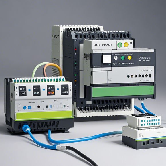
Mastering the Art of PLC (Programmable Logic Controller) Connection
In the world of industrial automation, programming logic controllers (PLC) is a vital skill for any engineer or technician. PLCs are designed to control and automate complex industrial processes, making them an indispensable tool in many industries.To effectively connect an PLC to a computer system, one must first understand the basic principles of PLC programming. This includes understanding the structure of the device, as well as the various types of communication protocols used to interface with the PLC.Once these foundational concepts are understood, one can move on to the actual process of connecting the PLC to the computer system. This typically involves using specialized software that allows for the creation and configuration of programs that control the PLC's operations.With proper training and practice, anyone can master the art of PLC connection. By investing time and effort into learning this skill, one can significantly increase their efficiency and effectiveness in their work, ultimately leading to greater success in their career.
As a forward-thinking exporter, understanding the intricate world of Plc (Programmable Logic Controllers) is crucial for ensuring seamless operation. A well-maintained PLC system can significantly boost your business's efficiency and productivity. Let's dive into the world of plc controller connections, exploring the basic principles, common types, and practical tips to master this essential skill.
At its core, a PLC is a powerful tool that allows for precise control over industrial processes. Its ability to program complex operations and execute them with precision makes it an indispensable component for any manufacturing or automation setup. The key lies in its connection to other systems, whether it be computers, sensors, or even human operators. In this tutorial, we'll explore the various ways in which PLCs interface with their surroundings, covering both hardware and software aspects.
Firstly, let's delve into the physical wiring aspect. When connecting PLCs, it's essential to have a clear understanding of what each component does. For instance, a sensor might send data on a process's state to a PLC, which then uses this data to make decisions. On the other hand, a pump could be controlled by a PLC, turning on and off based on specific parameters.

To begin with, you'll need to identify the sensors and actuators in your system, as these are the first points of contact between the PLC and the outside world. Once you have identified them, you can start drawing a diagram showing how they connect to the PLC. Remember to include all necessary components such as relays, switches, motor drives, and communication modules.
Next, consider the software side. PLC programs are written using a variety of programming languages like Ladder Logic, Function Block Diagrams, and Sequential Function Charts. Each language has its unique strengths and weaknesses, so it's important to choose one that suits the complexity of your project.
For example, if your PLC is controlling a conveyor belt, you might want to use Function Block Diagrams since they allow for more flexibility and ease of understanding. However, if you're working with a simpler system like lighting controls, Ladder Logic might be more suitable.
Once you have your software set up, it's time to test everything out in a simulated environment. This can be done using tools like LabVIEW or Siemens' WinCC, which allow you to create custom simulations to see how different inputs will affect your outputs.
Now that you're familiar with the basics of PLC connections, it's time to move onto some practical tips. Firstly, always follow safety guidelines when working with PLCs. Make sure all cables are properly grounded and avoid touching exposed wires. Secondly, practice regularly to improve your skills and familiarize yourself with the software and hardware tools available to you. Thirdly, don't be afraid to ask for help from colleagues or experts if you get stuck.
In conclusion, mastering the art of PLC connections requires dedication, patience, and a willingness to learn. By following our guide and practicing these tips, you'll be well on your way to becoming an expert in the field. Remember, every successful business starts with a strong foundation of reliable systems, and your PLC connections are no exception.

Content expansion reading:
As an experienced foreign trade operator, I am familiar with various industrial control systems, and the PLC (Programmable Logic Controller) is one of the most critical components in these systems. Today, I will focus on the PLC controller wiring diagram and provide a detailed explanation to help you understand its function and operation.
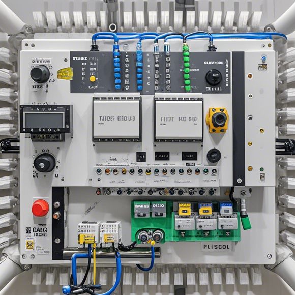
Firstly, let's start with a brief introduction to PLC controllers. PLCs are specialized industrial computers designed to monitor and control various machinery and processes in automated systems. They are widely used in manufacturing, processing, and other industrial applications. The PLC controller wiring diagram is a crucial document that outlines the connections between the PLC and other components in the system, such as input devices, output devices, and other controllers.
When examining a PLC controller wiring diagram, it is essential to understand the different components and their functions. The diagram typically includes a PLC unit, input devices (e.g., switches, sensors), output devices (e.g., motors, solenoids), and various connecting wires. The PLC unit is the brain of the system, receiving input signals from various sources and processing them according to the programmed logic.
To start the wiring process, it is crucial to identify the correct connections for each component. Input devices are connected to the PLC using wires that carry signals indicating the status of various processes or machines. For example, a switch might be connected to the PLC to indicate when a machine is on or off. Output devices are connected to the PLC using wires that carry control signals to operate various motors or actuators.
When connecting the PLC to other components, it is essential to follow the wiring diagram carefully. Incorrect wiring can lead to malfunctions or even damage to the PLC or other components. It is also important to ensure that the wiring is secure and properly insulated to prevent any short circuits or other electrical problems.

In addition to the basic wiring, it is also necessary to consider the power supply for the PLC and other components. The power supply should be connected according to the specifications of the equipment and should be properly grounded to ensure safety.
After the wiring diagram is complete, it is important to test the system to ensure that everything is working correctly. This testing should include checking the input and output signals to ensure that they are being properly received and transmitted by the PLC. If any problems are found during testing, it is necessary to check the wiring diagram again and make any necessary adjustments.
Overall, understanding and correctly implementing a PLC controller wiring diagram is crucial for the successful operation of any automated system. By following the steps outlined above, you can ensure that your system is properly wired and will operate efficiently and reliably. With experience and proper training, you will become proficient in reading and interpreting PLC controller wiring diagrams, allowing you to troubleshoot and maintain your systems effectively.
I hope this detailed explanation helps you understand the importance and implementation of PLC controller wiring diagrams. If you have any further questions or need assistance with specific diagrams, feel free to ask for help.
Articles related to the knowledge points of this article:
PLC Controller for Manufacturing Automation
The cost of a PLC Controller: A Comprehensive Analysis
PLC Programming for Automation Control in the Manufacturing Industry
How to Use a PLC Controller for Your Business
PLC (Programmable Logic Controller) Control System Basics
PLC Controllers: A Comprehensive Guide to Understanding Their Prices