Mastering the Art of PLC Control Cabinet Wiring Diagrams
Sure, I can help you with that. Here's a summary of your content in English:"To master the art of PLC (Programmable Logic Controller) control cabinet wiring diagrams, you need to first understand the basic concepts and terminology related to this field. This includes familiarity with various components like sensors, actuators, motors, etc., which play critical roles in controlling the system. Next, you need to have a thorough knowledge of the programming languages and algorithms used for programming PLCs, such as ladder logic, function blocks, and PID controllers. Once you have these foundational skills, you should focus on creating effective and efficient wiring diagrams that accurately represent the physical layout and connections of the control system. This involves using appropriate symbols, labels, and schematics to convey the intended functionality and interactions of the system components. Finally, it's essential to continuously update and revise your wiring diagrams based on changes in the hardware or software components, ensuring that they remain accurate and up-to-date throughout the life of the project."
In this age of automation, understanding and effectively managing PLC (Programmable Logic Controller) control cabinet wiring diagrams is crucial for any successful implementation. A plc (Programmable Logic Controller) is a device that can be programmed to autonomously control various industrial processes. It's an essential tool in today's manufacturing and engineering sectors, as it allows for precise, reliable, and efficient operation.
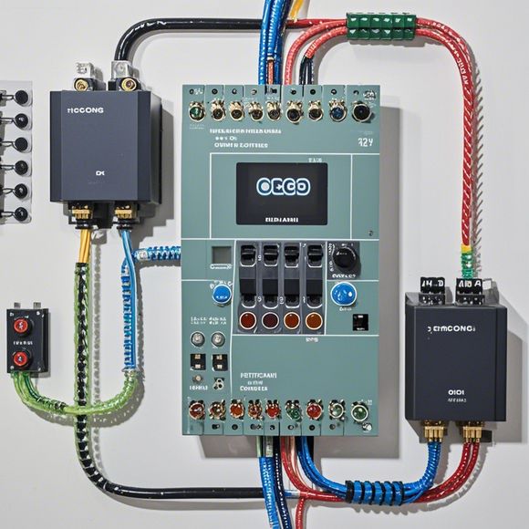
When working with plc control cabinets, it's important to have a thorough understanding of their wiring diagrams. These diagrams are typically provided by the manufacturers or engineers who design and install these systems. They show how the different components and wires are connected to each other, providing instructions for troubleshooting and maintaining the system.
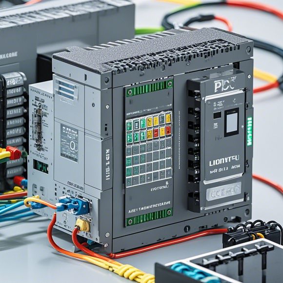
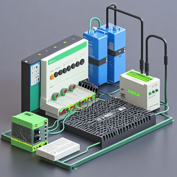
To start with, one must first familiarize themselves with the basic components found in a typical plc control cabinet. These include the CPU (Central Processing Unit), input/output modules, power supply, and communication interfaces such as Ethernet or PROFINET. The wiring diagram will show the connections between these components and the various sensors, actuators, and other devices used in the system. It will also indicate the type and voltage of the electrical connections, including grounding and protection measures.
Understanding the wiring diagram is crucial for ensuring that all devices are properly connected and that the system operates as intended. Mistakes in connection can lead to malfunctions, safety hazards, or even complete failure of the system. Therefore, it's essential to read and follow the instructions provided on the diagram carefully to prevent errors and ensure optimal performance.

In addition to the technical aspects of the wiring diagram, it's important to understand its purpose and how it fits into the larger system. This includes knowing what kind of data is being sent and received, as well as the types of sensors and actuators being utilized. Knowing these details can help identify potential issues early on and allow for more effective troubleshooting and maintenance.
Another key point to remember is the need for continual monitoring and updates of the plc control cabinet wiring diagrams. As new technologies and equipment become available, there may be changes in the system that require adjustments to the wiring diagram. It's important for professionals to stay up-to-date with these changes and make any necessary adjustments to ensure the system remains reliable and effective.
In conclusion, mastering the art of plc control cabinet wiring diagrams is essential for anyone looking to implement automated systems in their industries. By having a thorough understanding of these diagrams, professionals can avoid common pitfalls and maintain high levels of efficiency and reliability. So let's dive deeper into these intricate yet critical components and ensure they continue to drive our industries forward!
Content expansion reading:
Hello there, fellow foreign trade professionals! Today, let's delve into the fascinating world of PLC control cabinets and their wiring diagrams. As we navigate the realm of automation and technology, understanding the intricacies of PLC control cabinet wiring becomes crucial for any business involved in international trade.
Imagine a sea of cables, switches, and sensors, all converging at the heart of a machine or system - that's where the PLC control cabinet comes into play. It's the brain that receives input from various sources and sends out commands to ensure smooth operation. But behind all this, lies a complex maze of wiring that needs to be accurately installed and configured.

That's where our PLC control cabinet wiring diagrams come in handy. These diagrams are not just simple sketches; they're detailed guides that provide a comprehensive overview of how each wire should be connected and where. From the main power supply to the individual inputs and outputs, every detail is meticulously represented in these diagrams.
Now, let's take a look at what you can expect from our PLC control cabinet wiring diagrams:
1、Detailed Illustrations: Our diagrams provide detailed illustrations of various PLC control cabinet components, including switches, sensors, relays, and other critical components. This helps you understand how each part fits into the overall system.
2、Comprehensive List of Components: Our diagrams also include a comprehensive list of all the components used in the PLC control cabinet. This helps you identify which parts are needed for your specific application and ensures that you have everything you need for a successful installation.
3、Step-by-Step Installation Guide: In addition to the diagrams, we provide a step-by-step installation guide that explains how to connect each wire and component. This guide is written in a way that is accessible to anyone, regardless of their level of technical expertise.
4、Troubleshooting Tips: We also include troubleshooting tips that help you identify and resolve any issues during installation or operation. This is crucial for ensuring the smooth operation of your PLC control cabinet and avoiding costly downtime.

5、Expert Advice: Our diagrams come with expert advice from industry professionals who have years of experience in PLC control cabinet installation and wiring. This advice covers best practices, common pitfalls to avoid, and tips for optimizing performance.
By following our PLC control cabinet wiring diagrams, you can ensure that your installation is accurate, efficient, and reliable. This not only helps you save time and money but also ensures the safety of your personnel and the smooth operation of your machines or systems.
So, if you're involved in international trade and looking for a comprehensive guide to PLC control cabinet wiring diagrams, look no further! Our diagrams are designed to cater to your needs, no matter your level of technical expertise. Download our diagrams today and embark on your journey into the world of PLC control cabinets!
Articles related to the knowledge points of this article:
PLC Programming for Automation Control in the Manufacturing Industry
Plumbers Rule! The Role of PLC Controllers in the World of Waterworks
The Role of Programmable Logic Controllers (PLCs) in Foreign Trade Operations
Connecting a PLC Controller to Your Computer
PLC Controllers: A Comprehensive Guide to Understanding Their Prices