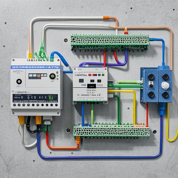
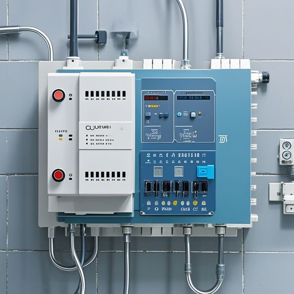
PLC Controller Principle Diagram
Sure, here's a summary in English for your PLC (Programmable Logic Controller) controller principle diagram:The PLC controller is a powerful device used in industrial automation to control and manage various processes. It consists of an array of input and output ports, which are connected to sensors or actuators that detect or manipulate physical variables. The controller receives data from these inputs and uses it to calculate the desired output value. This value is sent to the output ports where the appropriate devices respond accordingly.The principle diagram shows the connections between the various components, such as sensors, processors, memory modules, and communication interfaces. Each component has its own role in the system and interacts with other components through wired or wireless connections. The diagram also includes error handling circuitry to ensure that the system can recover from any failures or faults.Overall, the PLC controller plays a vital role in modern industrial applications by providing efficient and reliable control over complex systems.
As a foreign trade operation, understanding the principles of PLC controllers is crucial to ensure smooth operations and efficient control systems. Here's an overview of how to use English to describe the PLC controller principle diagram in a conversational manner:

Hello everyone, today we are going to discuss the PLC (Programmable Logic Controller) controller principle diagram. This diagram represents the internal workings of a PLC system, allowing us to understand how it communicates with various devices and performs tasks. So let's dive into the details.
Firstly, the PLC controller is a key component in industrial automation systems. It serves as the brain of the entire system, managing and controlling the flow of information between various components. The principle diagram shows the structure of the PLC, including its input/output ports, memory, processing circuits, and communication modules.
To start with, the input/output ports are the interfaces that allow PLCs to communicate with external devices. These ports can be wired or wireless, depending on the specific requirements of the application. For example, some devices may require sensor data to be transmitted wirelessly while others may require hardwired connections.
The memory section is crucial for storing program code and configuration settings. PLCs can run different programs at different times, so having enough memory space is essential. In addition, it's important to consider the size of the memory required based on the number of devices connected to the system.
The processing circuits are responsible for interpreting the input data and generating output signals. They typically include a microprocessor or digital signal processor (DSP). These components help PLCs analyze the data received from sensors or other devices and generate the necessary commands to control them.
Communication modules are also important components of the PLC system. These modules enable PLCs to connect to other devices in the system and transfer data between them. Some common communication protocols used in PLC systems include Ethernet, PROFINET, and PROFISYS.
Now, let's move onto the main topic of the day: the function of each component in the PLC controller principle diagram. The input/output ports are responsible for connecting external devices to the PLC system. For instance, they can be used to connect sensors, motors, and other devices to monitor and control their performance.
The memory section is where program code and configuration settings are stored. This allows PLCs to run different programs based on user preferences or changing conditions. Additionally, it's important to consider the capacity of the memory section when designing the system.

The processing circuits are crucial for interpreting data and generating output signals. They typically include a microprocessor or DSP that processes the data received from sensors or other devices and generates the necessary commands to control them.
Lastly, communication modules enable PLCs to connect to other devices in the system and transfer data between them. Some common communication protocols used in PLC systems include Ethernet, PROFINET, and PROFISYS.
In conclusion, the PLC controller principle diagram provides valuable insights into how a system works. By understanding each component's role, we can optimize the design and performance of our automation systems. Is there anything else you would like to know about PLC controllers?
Content expansion reading:
Here's a detailed,口语化的英文内容 based on the PLC controller schematic:
Looking at the PLC controller schematic, it's like reading a roadmap to automation success. This diagram is the blueprint for how the controller will handle inputs, process them, and deliver outputs, making our machines work smoothly and efficiently.
Starting from the input section, we have various sensors and devices that send signals to the PLC. These could be anything from temperature sensors to motion detectors, all sending vital data to the brain of the operation. The PLC then receives these inputs and starts processing them.
The processing section is where the magic happens. The PLC goes through its programmed logic, deciding what actions to take based on the incoming data. It's like a traffic cop, constantly evaluating the flow of information and making decisions to keep everything moving smoothly.

Then we have the output section, where the PLC sends signals to control various devices. This could be motors, valves, or any other equipment that needs to be controlled automatically. The PLC sends the right signal to the right place, ensuring that everything runs as it should.
But just having the schematic is just the beginning. Understanding how to interpret it and apply it in real-world situations is key. This is where our team's expertise comes in. We study the schematic, understand the flow of information, and identify any potential bottlenecks or issues. We then make adjustments, test the system, and monitor its performance.
Regular maintenance is also crucial. We check the schematic regularly, ensuring that all connections are secure and functioning properly. We also update the PLC's software, ensuring that it's running the latest and most efficient version.
Communication is essential when working with PLCs. We need to understand the language of the machine, which is why we study the schematic thoroughly. We also communicate with our team regularly, sharing insights, tips, and tricks to improve our efficiency and ensure that we're always up to date with the latest trends in automation.
In addition to all this, safety is always our top priority. We make sure that the PLC is operating within safe parameters and that any potential hazards are identified and addressed promptly. This ensures that our machines are not only running efficiently but also safely.
Overall, the PLC controller schematic is our roadmap to automation success. It's a living document that we constantly refer to, update, and learn from. As we continue to evolve and improve our machines, the schematic will continue to evolve with us, ensuring that our automation journey is as smooth as possible.
So there you have it – a detailed look at the PLC controller schematic and its operation, highlighting its importance in our daily work as外贸运营 professionals.
Articles related to the knowledge points of this article:
The cost of a PLC Controller: A Comprehensive Analysis
PLC Programming for Automation Control in the Manufacturing Industry
PLC (Programmable Logic Controller) Control System Basics
Plumbers Rule! The Role of PLC Controllers in the World of Waterworks
The Role of Programmable Logic Controllers (PLCs) in Foreign Trade Operations