Mastering the Art of Plc Controller Wiring Diagrams for Successful International Trade
In today's globalized economy, mastering the art of PLC control wiring diagrams is crucial for successful international trade. By understanding the complexities and nuances of electrical systems, you can ensure that your products are properly wired and function correctly in different markets.One of the main advantages of PLC controllers is their ability to automate industrial processes, making them highly efficient and cost-effective. Additionally, they offer high levels of flexibility, allowing you to customize solutions to meet specific needs.To succeed in international trade, it's important to have a good understanding of the electrical standards used in different countries. This means being familiar with local regulations and ensuring that your PLC control wiring diagrams comply with these standards.By investing time and effort into learning about PLC control technology and its applications, you can take advantage of the opportunities that come with international trade and build strong partnerships with clients around the world.
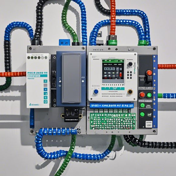
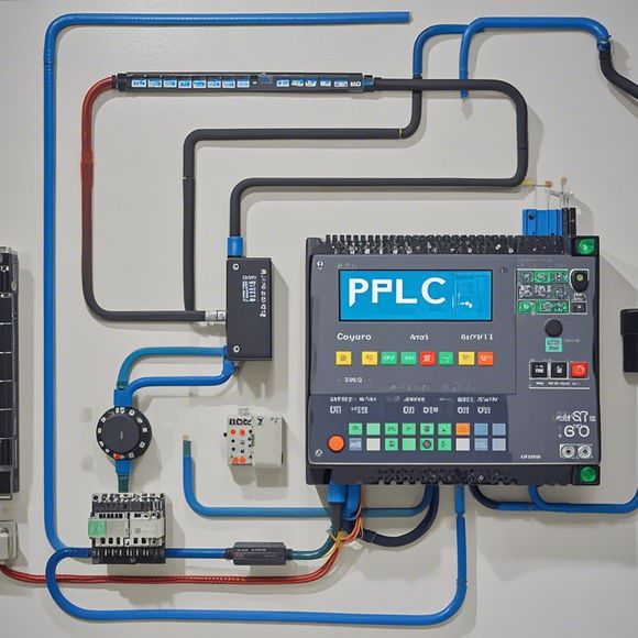
In the realm of international trade, understanding and mastering the intricate world of Plc (Programmable Logic Controller) controllers is crucial. These devices play a vital role in ensuring that manufacturing processes are run smoothly, with precision and efficiency. The plc controller wiring diagram, on the other hand, serves as a visual guide to understand how different electrical components interact and control each other.
To begin with, let's break down the basic structure of a Plc controller. It consists of several modules, including input modules, output modules, and logic modules, all of which communicate through wires. Each module has its own unique set of connections, and understanding these connections is essential for troubleshooting and debugging issues.
The first step in understanding a plc controller wiring diagram is to identify the various components such as sensors, actuators, and motors that are connected to the controller. Each component has a specific connection point, and knowing the exact location of these points helps in identifying potential issues. For example, if a sensor fails to provide accurate readings during testing, it might be due to an incorrect connection point or a faulty sensor itself.

Another important aspect of a plc controller wiring diagram is its complexity. There are many variables that can impact the wiring, including power levels, signal timing, and communication protocols. A skilled technician must be able to analyze these variables accurately and make appropriate adjustments to optimize performance. For example, if a particular sensor requires high-voltage power but is connected to a low-voltage supply, this could potentially damage the sensor or cause other unintended consequences.
Furthermore, it's essential to consider the safety aspects of a plc controller wiring diagram. Electrical hazards can occur if not properly secured or maintained. This includes ensuring that all connections are made securely using appropriate connectors, and that the wiring is protected from exposure to external elements such as moisture or dust. Additionally, regular inspections and maintenance are necessary to ensure that the system remains reliable and efficient.
In conclusion, mastering the art of Plc controller wiring diagrams takes more than just knowledge of technical details. It involves a deep understanding of the underlying principles, careful attention to detail, and a willingness to adapt to changing circumstances. As an international trade professional, having this expertise can help you navigate complex systems, troubleshoot issues efficiently, and achieve your goals with greater confidence.
Content expansion reading:
Hello there! Today, we're going to delve into the world of PLC controllers and their wiring diagrams. If you're new to this field or just looking for a refresh on the subject, this explanation is going to cover all the basics and help you understand how these controllers are connected.

First off, let's start with a brief overview of PLC controllers. PLC stands for Programmable Logic Controllers, which are essentially digital computers used in industrial automation systems. They monitor and control machines and processes, ensuring they operate as intended. The wiring diagram is a crucial part of this system, as it outlines how the various components are connected to the PLC.
Now, let's take a look at the PLC controller wiring diagram. At the center of this diagram, you'll find the PLC controller itself. Surrounding it are various inputs and outputs, which are connected to sensors, actuators, and other devices in the system. The inputs are basically signals from these devices that tell the PLC what's happening in the system, while the outputs are signals sent from the PLC to control other devices.
The wiring diagram will show you how these connections are made. Each wire will be labeled with its corresponding device or component, making it easy to understand where each wire goes. You'll also see different types of connectors, each designed for specific types of devices or applications.
When it comes to actually wiring up the PLC controller, it's important to follow the diagram closely. Each wire needs to be connected to the right terminal or port on the PLC, and if you connect the wrong wire to the wrong port, it could cause serious problems with the system. So, take your time and make sure you're connecting everything correctly.
Now that we've covered the basics of the wiring diagram, let's talk about some of the specific components you'll find on these diagrams. One of the most important components is the power supply. This is what provides power to the PLC controller and all its connected devices. You'll also see various input modules and output modules, which are responsible for receiving and sending signals to other devices in the system.

In addition to these components, you may also see other devices like sensors and actuators on the wiring diagram. Sensors are used to detect changes in conditions like temperature or pressure, while actuators are used to control things like motors or valves. These devices are connected to the PLC controller via input and output wires, respectively.
Finally, it's important to note that different PLC controllers may have different wiring diagrams depending on their specific applications or configurations. So, when you're working with a new PLC controller or trying to understand how a particular system is set up, it's always a good idea to refer to the manufacturer's documentation or consult with an experienced professional in the field.
In summary, understanding PLC controller wiring diagrams is essential for anyone working in industrial automation. By following this detailed explanation and referring to the manufacturer's documentation, you should be able to understand how these systems are set up and how to properly connect your PLC controller to other devices in your system. So, there you have it – a comprehensive overview of PLC controller wiring diagrams!
Articles related to the knowledge points of this article:
Mastering the Art of Plc Controllers: A Comprehensive Guide to Understand and Implement
PLC Controller Wiring Guideline
PLC Programming for Automation Control in the Manufacturing Industry