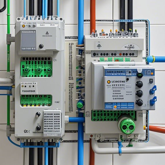
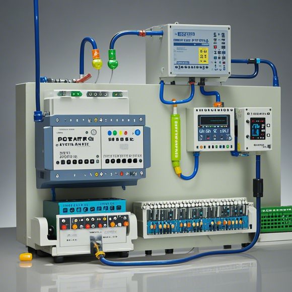
PLC Controller Wiring Diagram Interpretation for Import and Export Business
在进出口业务中,PLC控制器的接线图解释至关重要。PLC(可编程逻辑控制器)是现代工业自动化的核心,它通过精确的编程来控制机器的运行,提高效率和安全性。复杂的接线图可能会让新手感到困惑。以下是对PLC控制器接线图的一些基本解释:1. 输入信号:这些是传感器或操作员输入的数据,例如按钮、开关或其他类型的输入设备。输入信号通常以数字形式表示,如0和1。2. 输出信号:这是控制器执行的操作,如启动或停止某个设备。输出信号同样以数字形式表示,如高电平或低电平。3. 地址:地址是PLC内部用来识别不同输入和输出的信号的唯一标识符。每个信号都有一个特定的地址。4. 程序:PLC的程序是由一系列指令组成的,它们定义了如何响应不同的输入信号。程序通常存储在可擦除可编程只读存储器中。5. 通信:PLC可以通过各种方式与其他设备进行通信,如串行通信、以太网等。这有助于实现远程监控和维护。理解PLC控制器的接线图对于确保设备正常运行和优化生产过程至关重要。如果你对接线图有任何疑问,最好咨询专业人士或查阅相关文档。
Dear colleagues, today we are going to delve into the world of PLC controller wiring diagrams and how they can be used in our international trade operations. Let's start by understanding what a PLC (Programmable Logic Controller) is and how it operates within an industrial setting. A PLC is a device that allows you to program specific instructions to perform various tasks, such as controlling machinery or managing data flow within an organization. In an import and export business context, a PLC can be programmed to manage inventory levels, process orders, and ensure compliance with regulations such as customs requirements.
Now let's talk about wiring diagrams. These diagrams are visual representations of electrical connections within a system, often found in manufacturing plants or factory automation systems. They show how different components, such as sensors, switches, and motors, are connected together to form a functional system. For example, a wiring diagram might depict how a conveyor belt is wired up to feed material to a machine, or how sensors are connected to a control panel to monitor temperature or pressure levels.
In the context of import and export businesses, understanding these wiring diagrams is crucial for ensuring smooth operations and complying with regulatory standards. When dealing with foreign markets, knowing how to read and interpret these diagrams can help us identify potential issues early on, such as faulty wiring or improper installation. By understanding the components and their connections, we can troubleshoot issues more quickly and effectively.

One key aspect of wiring diagrams is their ability to communicate complex information in a simple way. By following the diagram, we can quickly determine which circuits need attention, such as those involving critical components like safety switches or alarm systems. This knowledge can save time and resources when debugging problems or making adjustments to the system.
Another important consideration is compatibility. As we expand our international trade operations, it's essential that we have a good understanding of the wiring standards used in different countries. This means not only knowing the language of the diagram but also the physical dimensions and electrical specifications of the components involved. By working with local partners or consultants who understand these standards, we can ensure that our systems are compatible and operate efficiently across borders.
In conclusion, PLC controller wiring diagrams are essential tools for any import and export business. By learning how to interpret these diagrams, we can better understand the complexities of our industrial systems and make informed decisions about equipment purchases, installation, and maintenance. Remember, a well-crafted diagram can save money in the long run by preventing costly downtime and ensuring compliance with international regulations. So let's take a moment to review our knowledge and practice what we've learned today, so we can continue to thrive in the ever-evolving landscape of international trade!
Content expansion reading:
Content:
Hey there! If you're new to the world of PLCs (Programmable Logic Controllers), or you're looking to brush up on your knowledge, understanding PLC controller wiring diagrams is a crucial step. These diagrams can seem intimidating at first, but once you know what to look for, they're actually pretty straightforward. In this guide, we'll break down the basics of PLC wiring diagrams in a way that's easy to understand, so you can confidently interpret them and get your systems up and running.
First things first, let's talk about what a PLC controller wiring diagram is. It's a visual representation of the electrical connections between the various components of a PLC system. This includes the power supply, the PLC itself, input devices (like sensors), output devices (like actuators), and any other peripherals. The diagram will show you where each wire should go and what function it serves.
When you're looking at a PLC controller wiring diagram, you'll typically see a few key elements:
1、Power Supply: This is where the electrical power enters the system. You'll see lines indicating the incoming power and how it's distributed to the PLC and other components.

2、PLC Chassis: This is the main body of the PLC, where all the internal components are housed. The wiring diagram will show how the power is connected to the PLC and how the I/O (Input/Output) modules are connected.
3、Input Devices: These are the sensors or switches that provide data to the PLC. They're usually connected to the PLC's input terminals.
4、Output Devices: Actuators, motors, or lights that receive commands from the PLC are connected to the output terminals.
5、I/O Modules: These are expansion modules that can increase the number of inputs and outputs available to the PLC.
6、Terminal Blocks: These are the physical connectors where wires are attached. They're often color-coded to indicate different types of signals.
7、Jumpers: These are short pieces of wire used to connect points on a circuit board without using a cable. They're used to configure the PLC as needed.
8、Diagnostics: Some diagrams may include components related to system diagnostics, like test points or fault indicators.
To read a PLC controller wiring diagram, you should follow these steps:
Identify the Components: Look for labels or symbols that represent the different parts of the system.

Understand the Symbols: Each component and connection will be represented by a specific symbol. Make sure you know what these symbols mean.
Follow the Lines: Trace the lines from one component to another to understand how they're connected.
Check the Wire Numbers: Wires are often numbered to help identify them. Make sure the numbers on the diagram match the numbers on the wires.
Consult the Legend: Every wiring diagram should have a legend that explains the meaning of the symbols and colors used.
Check for Grounding: Make sure the diagram shows how the system is grounded to prevent electrical shock and ensure safety.
Look for Notes: Manufacturers often include additional notes or instructions on the diagram that are important for proper installation and operation.
Remember, safety is paramount when working with PLCs and electrical systems. Always follow proper safety procedures, including wearing the appropriate personal protective equipment (PPE) and ensuring the power is off before making any connections.
By understanding PLC controller wiring diagrams, you'll be able to install, troubleshoot, and maintain PLC systems with confidence. Whether you're a seasoned pro or just starting out, this knowledge is essential for success in the world of industrial automation.
Articles related to the knowledge points of this article:
PLC Controller Selection Guide for Foreign Trade Operations
The cost of a PLC Controller: A Comprehensive Analysis
PLC Programming for Automation Control in the Manufacturing Industry
PLC (Programmable Logic Controller) Control System Basics
The Role of Programmable Logic Controllers (PLCs) in Foreign Trade Operations