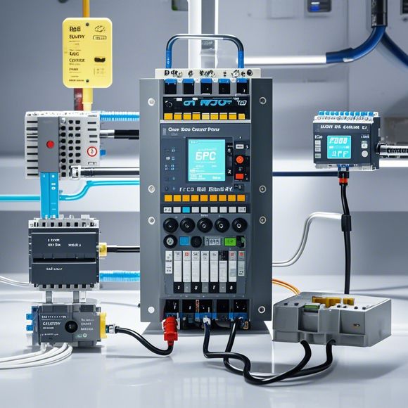
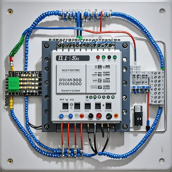
PLC Control System Principle Diagram
The principle diagram of the PLC (Programmable Logic Controller) control system is a visual representation that outlines how the system works. It typically includes components such as sensors, actuators, processors, and communication networks. The diagram shows the input signals from the sensors, which are then processed by the processor to generate output signals that drive the actuators. The processor communicates with other devices through network connections to ensure that all parts of the system work together seamlessly. Overall, the principle diagram provides a clear understanding of how the PLC control system functions and helps engineers design and maintain the system.
Introduction to PLC (Programmable Logic Controller) System Design and Application
In today's world, the importance of automation cannot be overstated as it plays a crucial role in various manufacturing industries. A programmable logic controller (PLC) system is one of the most popular and effective tools for implementing automated control systems. This system allows precise control of various industrial processes by programming them with algorithms that mimic human-like decision-making. The PLC system is designed to handle complex tasks, such as controlling valves, motor speeds, temperature settings, and more, all while providing an efficient and reliable solution to industrial automation. In this guide, we will delve into the fundamentals of designing an PLC system using its principle diagram.
Understanding the PLC Principle Diagram

The principle diagram of a PLC is a visual representation of the system's components and how they interact with each other. It provides a clear understanding of the system's architecture and the different functions performed by each component. The diagram consists of several key elements such as input devices, processing elements, output devices, and communication networks.
Input Devices
Input devices are essential for capturing data from the environment or external sources. They include sensors, switches, and actuators, which can measure physical quantities such as temperature, pressure, or position. These devices provide real-time feedback on the state of the system. For instance, a temperature sensor can detect fluctuations in temperature and send a signal to the PLC, allowing it to adjust the heating system accordingly.
Processing Elements
The processing elements are responsible for analyzing the data received from the input devices and performing calculations or actions based on the results. These elements may include microprocessors, field-programmable gate arrays (FPGAs), and dedicated software applications. By processing the data, the processing element determines the next steps in the process and communicates them to the output devices. For example, if the temperature reading indicates that it exceeds safe levels, the processing element could activate a safety feature to prevent potential damage.
Output Devices
Output devices are responsible for sending commands to external systems, such as motors, lights, or valves, depending on the action triggered by the processing element. These devices can be physical switches, relays, or even LEDs or motors. For instance, when the PLC receives a command to increase the flow rate of a pump, it would activate the motor to increase the pressure, resulting in a higher water flow.
Communication Networks
Communication networks are the backbone of any PLC system. They enable the exchange of information between different components of the system. The network may consist of wired connections or wireless technologies, such as Ethernet, Wi-Fi, or Bluetooth. The network ensures that the processing element receives data from the input devices, analyzes it, and sends the necessary commands to the output devices in real time. For example, if the input device detects a change in a chemical concentration, the PLC would use the communication network to trigger automatic alarms or initiate emergency procedures.

Design Considerations for an Effective PLC System
When designing an PLC system, there are several considerations that must be taken into account to ensure optimal performance and efficiency. Firstly, the system's architecture should be chosen based on the specific requirements of the application. This includes selecting appropriate hardware components, such as input/output modules, processors, and memory banks, and determining the number and type of communication networks required. Secondly, the system's programming language must be chosen based on the application's needs and the expertise of developers. This involves selecting a language that is easy to read, write, and modify, and that supports the desired functionality. Thirdly, the system's testing phase is critical to ensuring that the design meets all specified requirements and performs efficiently under different conditions. Testing should include both functional tests and performance tests, covering various scenarios such as high loads, low loads, and faulty inputs. Finally, regular maintenance and updates should be implemented to ensure that the system remains up-to-date with the latest developments and improvements in hardware and software technologies.
Conclusion
The PLC system is a powerful tool for implementing automated control systems that enable precise control over various industrial processes. By following the principles outlined in this guide and considering the key factors such as input devices, processing elements, output devices, communication networks, and design considerations, you can create an effective PLC system that meets the specific needs of your industry. Remember that investing in quality hardware and software components, and regular testing and maintenance are essential for maintaining optimal performance and reliability of your PLC system.
Content expansion reading:
Content:
Hey there! If you're new to the world of PLCs (Programmable Logic Controllers), or you're looking to brush up on your knowledge, understanding PLC control system wiring diagrams is a crucial step. These diagrams are the blueprint that tells you how all the components of a PLC system are connected and how they work together. In this post, we're going to dive in and break down what you need to know to make sense of these diagrams.
First things first, let's talk about what a PLC control system is. Imagine a factory floor with all sorts of machines running. A PLC is like the brain that tells these machines what to do and when to do it. It's a ruggedized computer designed to withstand the harsh conditions of an industrial environment.
Now, let's get to the wiring diagrams. These diagrams are a visual representation of the electrical connections between the PLC and all the devices it controls, like sensors, motors, and lights. They're designed to be clear and easy to read, so you can quickly understand how the system is put together.

The heart of the diagram is the PLC itself. This is where the magic happens. The PLC has inputs and outputs (I/O). Inputs are where the PLC gets information from the environment, like a sensor detecting when a door is open. Outputs are where the PLC sends signals to control something, like turning on a motor.
On the diagram, you'll see symbols for these inputs and outputs. Inputs might be represented by switches or photosensors, while outputs could be relays or direct solenoid control. Each symbol has a specific meaning and is standardized across the industry to make things clear and consistent.
The wiring between these components is also clearly shown. You'll see lines connecting the PLC to the various devices, and these lines will have numbers or letters that correspond to specific wires in the system. This makes it easy to trace a signal from its source to its destination.
One important thing to look for on the diagram is the power supply. This is what keeps the PLC and all the connected devices running. You'll see the voltage and amperage ratings on the diagram, which are crucial for ensuring that you're using the right size and type of wire.
Another key element is the control panel. This is where the operator can interact with the system, often through buttons and switches. The control panel is usually connected to the PLC through a series of terminals, and this connection is clearly marked on the diagram.
Now, let's talk about safety. PLC control systems often have built-in safety features, and these will be clearly indicated on the wiring diagram. Look for devices like emergency stop buttons or safety interlocks that are designed to shut down the system in case of an issue.
When you're looking at a PLC control system wiring diagram, it's also important to understand the logic behind it. This is where the "programming" side of PLCs comes in. The PLC uses a program to interpret the inputs and decide what to do with the outputs. This program is often stored on a removable memory card, making it easy to update or troubleshoot if needed.
In summary, PLC control system wiring diagrams are a vital tool for anyone working with industrial automation. They provide a clear and detailed view of how all the components fit together, from the PLC to the sensors and actuators. By understanding these diagrams, you can effectively maintain, troubleshoot, and improve these systems. So the next time you come across one of these diagrams, you'll be ready to decode it with confidence!
Articles related to the knowledge points of this article:
Smart Manufacturing Solutions with PLC Integrated Machinery
PLC Controller Selection Guide for Foreign Trade Operations
Mastering the Art of Plc Controllers: A Comprehensive Guide to Understand and Implement
How to Use a PLC Controller for Your Business
PLC (Programmable Logic Controller) Control System Basics
Plumbers Rule! The Role of PLC Controllers in the World of Waterworks