plc实物接线大全
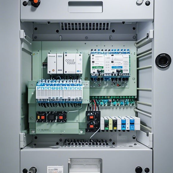
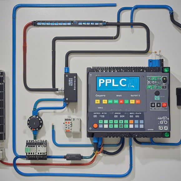
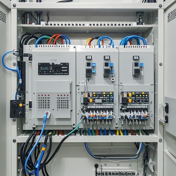
**Summary: The PLC Physical Wiring Overview**The physical wiring of PLC (Programmable Logic Control) plays a crucial role in the operation and maintenance of industrial automation systems. In this summary, we will introduce the main methods for connecting the input and output ports of the PLC.For input modules, the most common types are switches such as magnetic and optical sensors, which require specific wiring techniques to ensure accurate signal transmission. For instance, in a typical magnetic sensor circuit, Blue (blue) is connected to GND (ground), while Brown (brown) is connected to the input terminal X. Similarly, for optical sensors, Blue is connected to GND and Black to X.When it comes to output modules, COM (common) and Y (output) are commonly selected for their direct connection to the power source. The selection of COM and Y terminals is crucial as they directly affect the control signals' strength and reliability.Moreover, when dealing with more complex systems, it's essential to consider power supply and grounding connections. It's recommended to use a reliable power supply like Taiwan-made "Mingwei" switches, ensuring the safety of both the system and personnel.In conclusion, mastering the physical wiring of PLCs involves understanding the basic principles, selecting appropriate connections, and addressing potential issues during installation and operation. By following these steps and precautions, one can effectively connect and operate PLC systems, ensuring the smooth operation and longevity of industrial equipment.
"Mastering the Art of PLC (Programmable Logic Controller) Connections for Successful Foreign Trade Operations"
Introduction:
As a seasoned trader in international markets, it's essential to have a deep understanding of the intricate world of Programmable Logic Controllers (PLCs), which play pivotal roles in automation and control systems. Whether you're dealing with manufacturing processes or logistics operations, PLCs are the silent heroes behind the scenes that keep your business running smoothly. In this guide, we'll delve into the world of PLCs and how they connect with one another to create a cohesive system that meets your needs.
Understanding PLCs:

A PLC is a powerful device that can perform a wide range of functions, from simple logic controls to complex industrial processes. It's designed to be programmable, allowing you to tailor its behavior to meet specific requirements. Unlike mechanical switches, PLCs can respond to inputs from sensors, actuators, and other digital signals, making them ideal for modern automation applications.
Connecting PLCs:
The key to successfully connecting PLCs lies in understanding their communication protocols and how they interact with each other. Here's a step-by-step guide to help you get started:
1、Identify the Hardware: The first step is to identify the PLC hardware components involved in your automation system. This may include input/output devices, sensors, actuators, switches, and more. Once you have a clear understanding of these components, you can start planning how they will be interconnected.
2、Select the Right PLC Model: Based on the requirements of your automation system, choose an appropriate PLC model that can handle the load efficiently. Consider factors like processing power, memory capacity, and network connectivity when making your selection.
3、Establish Communication Channels: Once you have identified your PLC hardware, establish communication channels between them using suitable cables and connectors. These channels should be properly shielded to prevent interference and ensure reliable communication.
4、Configure the PLC Program: With your PLC hardware set up, it's time to configure the program. This involves writing code that defines the behavior of your automation system. Use high-level languages such as LabVIEW, C#, or Python for programming, depending on your specific needs. Remember to test your program thoroughly before implementing it on a live system.
5、Test the Connection: After configuring the PLC program, test the connection to ensure that all components work together seamlessly. This may involve testing individual components or running simulations to see how they interact with one another.
6、Monitoring and Maintenance: Finally, monitor the performance of your automation system regularly and address any issues that arise promptly. Keeping your PLCs updated with the latest patches and software can also help improve their reliability and efficiency over time.

In conclusion, mastering the art of PLC connections requires a combination of knowledge, experience, and careful attention to detail. By following the steps outlined above, you can create a robust and efficient automation system that meets the specific needs of your foreign trade operations. So why wait? Start building the future of international trade today!
Content expansion reading:
Content:
Hey there! If you're new to the world of programmable logic controllers (PLCs) and feeling a bit overwhelmed by the thought of wiring them up, don't worry! I'm here to guide you through the basics with a comprehensive look at PLC wiring diagrams. Whether you're a student, a DIY enthusiast, or just starting in the industry, this guide is for you.
So, what exactly is a PLC? It's a type of industrial computer designed to control and automate various electromechanical processes. They're tough, reliable, and can handle a wide range of tasks. But before you can get a PLC up and running, you need to know how to wire it properly. That's where wiring diagrams come in.
A wiring diagram is a visual representation of the connections between the PLC and its input/output devices. It's like a blueprint that tells you where to connect each wire and what those wires are doing. Understanding these diagrams is crucial for ensuring your system works correctly and safely.
Let's start with the basics. A typical PLC system has three main components: the PLC itself, input devices (like sensors and switches), and output devices (like motors and lights). The wiring diagram will show you how to connect these components together.
First, you'll see a power supply section. This is where you'll connect your mains power to the PLC. Always make sure to use the correct voltage and follow the safety guidelines provided by the manufacturer.
Next, you'll see the input devices. These are usually represented by symbols for different types of sensors or switches. The wiring diagram will show you which terminals on the PLC correspond to which inputs.

Output devices are represented similarly, with symbols for motors, lights, or other devices. The diagram will show you how to connect these to the PLC's output terminals.
It's important to note that PLCs can have different types of inputs and outputs, such as digital, analog, and special function modules. Each will have its own specific wiring requirements, so make sure you're familiar with the types of devices you're working with.
When you're looking at a wiring diagram, pay close attention to the labels and symbols. Each one represents a specific component or function. For example, a circle with a line through it is a switch, while a triangle with a line through it is a normally open contact.
As you become more familiar with PLC wiring diagrams, you'll start to see common patterns and understand the logic behind the connections. This will help you troubleshoot problems and make changes to the system more efficiently.
Remember, safety is paramount when working with electrical systems. Always ensure that the power is off before making any connections, and use the right tools and equipment for the job.
By the end of this guide, you should have a solid understanding of PLC wiring diagrams and be ready to tackle your first project with confidence. Happy wiring!
Articles related to the knowledge points of this article:
The Role of Programmable Logic Controllers (PLCs) in Foreign Trade Operations
Connecting a PLC Controller to Your Computer
PLC Controllers: A Comprehensive Guide to Understanding Their Prices