Pluggable Logic Controller (PLC) Wiring Diagram for Beginners
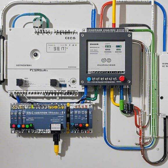
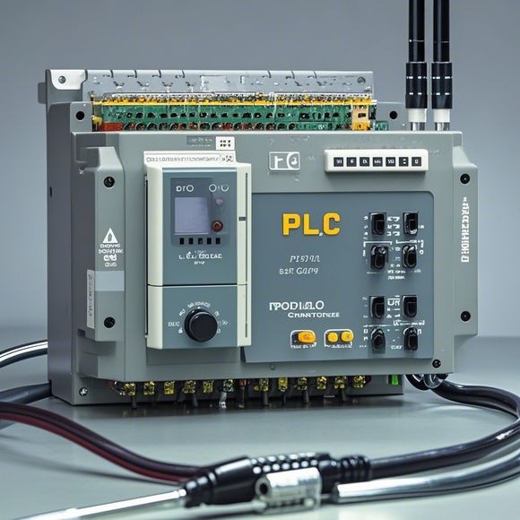
Pluggable Logic Controller (PLC) Wiring Diagram for BeginnersFor beginners in PLC wiring, a pluggable logic controller (PLC) wiring diagram is a valuable tool to understand the basic components and connections. This diagram typically consists of several key sections: the input section, output section, and the main control panel. The input section is responsible for receiving sensor or signal inputs from various sources, such as switches, relays, or other devices. The output section includes the power supply for driving motors, lights, or other actuators. Finally, the main control panel is where you can set up the program code that controls the flow of signals through the PLC. To get started, familiarize yourself with the different types of connectors used in PLC wiring, such as 24-pin connectors and 14-pin connectors. Once you have these tools, you'll be able to create your own pluggable logic controller wiring diagram and customize it to fit your specific application needs.
Introduction:
Welcome to the world of PLC wiring! Today, we're going to walk you through the process of connecting a plc controller to your electrical system. This guide is designed for beginners who want to understand how to wire their first PLC device and ensure that everything works smoothly. So let's get started!
Step 1: Gather Your Tools and Materials
Before we dive into the wiring process, make sure you have all the necessary tools and materials on hand. You'll need an electrician's multimeter, a soldering iron, wires, connectors, and some other miscellaneous items. Also, make sure your plc controller and electrical panel are in good condition before starting the wiring job.

Step 2: Disconnect the Existing Wires
Before you begin, it's important to disconnect any existing wires that may be connected to your existing electrical system. This will help prevent accidental short circuits or damage to your new components. Use caution when handling the wires and follow the manufacturer's instructions carefully.
Step 3: Measure and Cut the Wire
Using the measuring tool, measure the length of each wire you'll need to connect your PLC device. Then cut off the excess length using a wire stripper. Make sure to use a straight edge and a sharp blade to avoid damaging the wires.
Step 4: Connect the PLC Device to the Electrical Panel
Now it's time to connect your PLC device to the electrical panels. Start by connecting the positive terminal of the PLC device to the corresponding positive terminal of the panel. Next, connect the negative terminal of the PLC device to the corresponding negative terminal of the panel. Make sure all connections are secure and tight.
Step 5: Connect the Power Supply
Connect the power supply to the PLC device. Ensure that the power cords are securely fastened onto the PLC device and electrical panels. Check if there are any loose connections or damaged parts and replace them immediately.
Step 6: Test the Connections

Once all connections are complete, test the connection to see if it's working correctly. Use an electrician's multimeter to check for continuity between the PLC device and the panels. If you see a reading that's not as expected, reconnect the wires or try different combinations until everything works properly.
Step 7: Install the Programmable Logic Controller (PLC) Software
After ensuring that the physical connections are secure, it's time to install the software for your PLC device. Follow the instructions provided by the manufacturer for installing the software on your computer or laptop. Once installed, you should be able to control the functions of your PLC device from a user interface.
Conclusion:
With these steps, you've successfully completed your first wiring project using a plc controller. Remember, safety is always the top priority when working with electrical systems. Wear appropriate gloves, eye protection, and take extra precautions when handling wires and components. Happy wiring!
Content expansion reading:
Content:
Hey there! If you're new to the world of PLCs (Programmable Logic Controllers), or you're just looking to brush up on your knowledge, understanding PLC controller wiring diagrams is a crucial step. These diagrams can seem intimidating at first, but once you know what to look for, they're actually pretty straightforward.
So, what exactly is a PLC controller wiring diagram? It's a visual representation of the electrical connections between the various components of a PLC system. This includes the power supply, input devices, output devices, and the PLC itself. The diagram shows you how these components are connected and how they interact with each other.

When you're looking at a PLC controller wiring diagram, the first thing you'll notice is that it's divided into different sections. The power supply section is usually at the top, followed by the input devices, the PLC, and finally, the output devices. Each section is labeled clearly, so you can easily identify what's what.
Input devices are the sensors that provide data to the PLC. They can be switches, buttons, temperature sensors, or any other device that sends a signal to the PLC. Output devices, on the other hand, are the ones that receive signals from the PLC and perform an action. This could be turning on a motor, activating a solenoid, or controlling a valve.
The PLC itself is the brain of the system. It's where the programming logic lives, and it's responsible for interpreting the input signals and deciding what to do with them. The PLC will then send output signals to the appropriate devices to control the process.
Now, let's talk about the actual wiring. The diagram will show you the wires that connect each component. Wires are typically color-coded to indicate their function. For example, red wires often indicate power, while black or blue wires are usually used for control circuits. The diagram will also show you the wire gauge, which is important for ensuring that the wire can handle the current required for the device it's powering.
One key thing to remember is that PLC controller wiring diagrams are designed to be read from left to right and top to bottom. This makes it easier to follow the flow of the system. As you're reading the diagram, you should be able to trace the path of a signal from the input device to the PLC and then to the output device.
It's also worth noting that PLC controller wiring diagrams often include safety features, like emergency stop buttons or overload protection. These are designed to prevent accidents and damage to equipment.
In summary, PLC controller wiring diagrams are essential for ensuring that your PLC system is set up correctly and that it's safe and efficient. By understanding how to read these diagrams, you'll be better equipped to troubleshoot issues, make repairs, and even expand your system in the future. So, take some time to study them, and you'll be on your way to becoming a PLC pro!
Articles related to the knowledge points of this article:
Smart Manufacturing Solutions with PLC Integrated Machinery
Mastering the Art of Plc Controllers: A Comprehensive Guide to Understand and Implement
How to Use a PLC Controller for Your Business
PLC (Programmable Logic Controller) Control System Basics
Plumbers Rule! The Role of PLC Controllers in the World of Waterworks
PLC Controllers: A Comprehensive Guide to Understanding Their Prices