PLC Physical Connections Guide in English
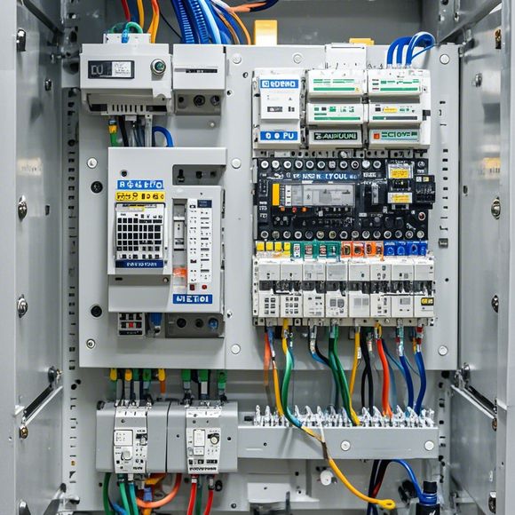
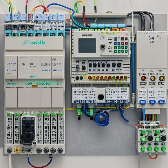
In this PLC (Programmable Logic Controller) physical connection guide, we will delve into the essential steps for establishing reliable and efficient connections between components within a PLC system. This guide aims to provide a comprehensive understanding of the various types of connections that can be made, as well as the importance of proper wiring practices for ensuring longevity and reliability of your PLC system.The first step is to understand the basic components of a PLC, such as sensors, actuators, and communication modules. Each of these components requires specific connections for optimal functionality. For example, sensors need to be connected to their corresponding output pins on the PLC board, while actuators require power and signal lines for proper operation.Once you have identified the necessary connections, it is important to follow the manufacturer's recommended wiring diagrams. These diagrams should include information on the type of cables to use, the appropriate voltage levels, and any special connectors or interfaces needed for different types of devices.It is also important to ensure that all connections are securely made using insulated screws and wire nuts. This helps prevent short circuits and potential damage to the PLC board or other components. Finally, regular maintenance checks should be performed to identify any issues with the connections or the wiring itself.
As an experienced foreign trade operator, I understand the importance of understanding and mastering the physical connections between various components when it comes to programmable logic controllers (PLCs). In this comprehensive guide, we will provide you with a detailed overview of how to connect the various components of a PLC to ensure smooth operation and maximum efficiency.
Firstly, let's take a closer look at the different types of PLCs that are commonly used in various industries such as manufacturing, industrial automation, and even in smart homes. Each model comes with its unique set of capabilities and features that cater to specific needs. For instance, some models are more focused on speed and performance, while others prioritize cost-effectiveness and ease of use.
Now, let's delve into the world of physical connections. When it comes to connecting PLCs, there is no one-size-fits-all approach. The key factor that determines the type of connection needed is the type of sensor or actuator that is being interfaced with the PLC. This can range from simple wired connections to more complex wireless or Bluetooth connections.

To start off, if you are dealing with sensors, you will need to connect them to the PLC using appropriate wiring harnesses. These harnesses should be designed according to the manufacturer's specifications, ensuring that the signal level and power requirements are met. Once connected, you can test the connection to ensure that data is being transferred properly.
Next, when it comes to connecting actuators, there are several options available. One popular method is to use solenoid valves or motor-driven devices that can be directly plugged into the PLC's output ports. Another option is to use stepper motors or pneumatics which require additional control modules to operate correctly. You should always refer to the manufacturer's documentation for specific details on how to connect these devices to your PLC.
In addition to sensors and actuators, there are other components that can be connected to a PLC. For example, temperature sensors, pressure sensors, and motion sensors can all be integrated into the system using appropriate hardware and software. It is important to ensure that these connections are securely made and tested before finalizing the design.
When it comes to programming, PLCs are highly flexible tools that can be programmed in a wide range of languages. Some common ones include ladder logic, structured text, and function blocks. The choice of language depends on the complexity of the project and the expertise of the team working on it. It is essential to choose a language that is easy to read, write, and maintain to ensure that the code is error-free and efficient.
Once the physical connections are established and the programming is complete, it is time to test the system. This involves running tests and monitoring the performance of each component to ensure that everything is operating as expected. It is also important to note that some components may require additional configuration settings to work correctly. These settings should be carefully documented and shared with the team working on the project.
Finally, once the system is thoroughly tested and ready to go live, it is time to implement it. This involves setting up the network infrastructure and configuring the communication protocols to ensure that the PLC is communicating with other systems effectively. It is important to follow best practices for network security and encryption to protect sensitive data from unauthorized access.
In conclusion, understanding and mastering the physical connections between PLCs is crucial for any successful project. By following the steps outlined above and consulting with professionals in the field, you can create a reliable and efficient system that meets the needs of your customers and clients. Remember that every project is unique, so it is essential to customize the process as per your requirements to achieve optimal results.
Content expansion reading:
Content:
Hey there! If you're new to the world of programmable logic controllers (PLCs) and feeling a bit overwhelmed by the thought of wiring them up, don't worry! I'm here to guide you through the basics with a comprehensive look at PLC wiring diagrams. Whether you're a student, a DIY enthusiast, or a professional just starting out, this guide is for you.
So, what exactly is a PLC? In simple terms, it's a type of industrial computer designed to control and automate various processes. They're tough, reliable, and can handle a wide range of tasks, from controlling a simple machine to managing a complex manufacturing plant.
When it comes to wiring a PLC, the key is to understand the different components and how they connect. Let's start with the basics:
1、Power Supply: Your PLC needs power to function, so you'll need to connect it to a reliable power source. Most PLCs use either 24V DC or 110V AC power. Make sure to connect the correct wires to the correct terminals.
2、Inputs: These are the devices that send signals to the PLC. They can be switches, sensors, or any other device that tells the PLC to perform an action. Inputs are usually connected to the PLC's input terminals.

3、Outputs: Outputs are the devices that the PLC controls. This could be a motor, a light, or any other electrical device. Outputs are connected to the PLC's output terminals.
Now, let's talk about wiring diagrams. These diagrams are like blueprints for your PLC setup. They show you how to connect all the components together correctly. Here's what you need to know:
Functional Diagram: This is a high-level overview of the system, showing the main components and their relationships.
Wiring Schematic: This is a detailed diagram that shows the exact connections between all the components.
Control Circuit: This diagram focuses on the control aspect of the system, showing how the PLC interacts with the inputs and outputs.
When reading a wiring diagram, you'll see a variety of symbols representing different components. For example, a switch might be represented by a rectangle with two lines inside, while an output might be a circle with a line and a plus sign. Make sure to familiarize yourself with these symbols to understand the diagram better.
Safety is paramount when working with PLCs and electrical systems. Always follow these safety tips:
Grounding: Ensure that all equipment is properly grounded to prevent electric shock.
Fuses and Breakers: Install appropriate fuses and circuit breakers to protect against electrical overload.
Isolation: Regularly isolate parts of the system when troubleshooting to prevent accidental energization.
Remember, practice makes perfect. The more you work with PLC wiring diagrams, the more comfortable you'll become with the process. Don't be afraid to start small with simple projects and work your way up to more complex ones.
Lastly, if you get stuck or need some extra help, there are plenty of resources available. Online forums, textbooks, and even YouTube tutorials can provide guidance and answer any questions you might have.
So, grab your tools, stay safe, and have fun exploring the world of PLCs. With a bit of knowledge and a lot of patience, you'll be wiring up your own PLC systems in no time!
Articles related to the knowledge points of this article:
PLC Programming for Automation Control in the Manufacturing Industry
Plumbers Rule! The Role of PLC Controllers in the World of Waterworks
The Role of Programmable Logic Controllers (PLCs) in Foreign Trade Operations
Connecting a PLC Controller to Your Computer
PLC Controllers: A Comprehensive Guide to Understanding Their Prices