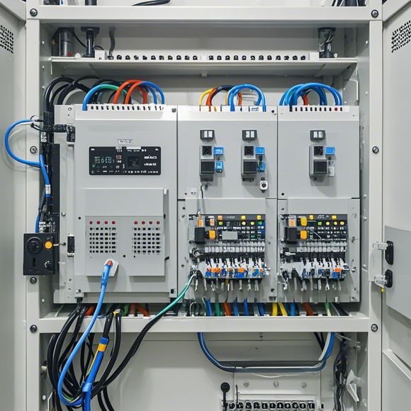
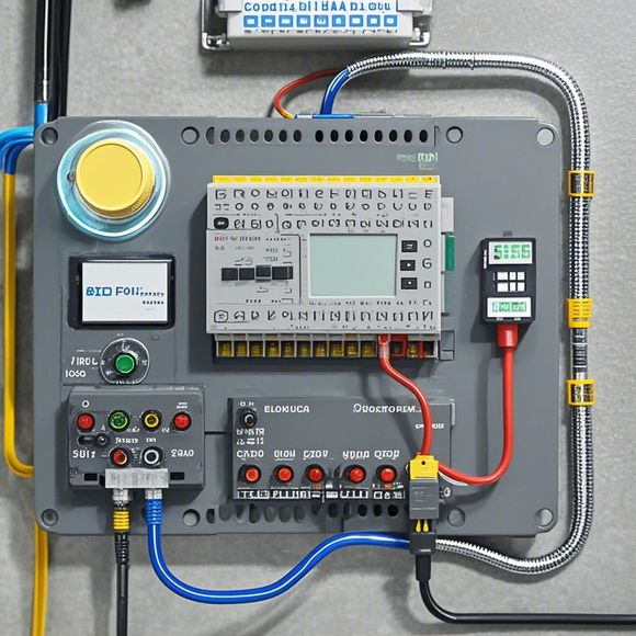
PLC (Programmable Logic Controller) Controller Wiring Guide for Your Import and Export Business
As an import and export business, you may be dealing with a plethora of PLC (Programmable Logic Controller) controllers. It's important to have a clear understanding of how these devices are wired for optimal performance. Here is a simple wiring guide for your convenience:1. Begin by connecting the power supply to the controller through the proper voltage and current specifications. Ensure that the power supply is compatible with the controller's power requirements.2. Connect the controller to the appropriate input and output devices. The input devices will receive signals from sensors or other devices, while the output devices will send commands to actuators or relays.3. Use a suitable cable type for each connection. For example, high-speed connections should be made with copper cables, while low-voltage connections can be made with fiber optic cables.4. Test the wiring regularly to ensure proper functioning of all devices. If any issues arise, address them promptly to prevent any potential problems.By following this simple wiring guide, you can ensure that your PLC controllers are wired correctly for efficient operation.
Hello everyone, today I'm going to guide you on how to wire up a plc controller for your import and export business. As a foreign trade operator, having a reliable control system is essential for maintaining the smooth running of your operations. A well-wired plc controller can ensure that your production lines or supply chain processes run efficiently and accurately. So, let's dive into the details of how to connect your plc controller to different components in your business.
First off, it's important to understand what an PLC is before we start wiring. An PLC stands for Programmable Logic Controller, and it's a device that allows you to program specific sequences of actions based on inputs from various sensors and actuators. In your business, an PLC can handle tasks like controlling machinery, monitoring inventory levels, or even managing customer data.
Now, let's talk about the basics of wiring up an PLC controller. You will need to connect the plc's power source to a suitable electrical panel, which should be grounded properly. Then, you will need to connect the PLC itself to the appropriate power and data cables. The first thing you need to do is identify the type of cable you need. There are two types of cables: AC (alternating current) and DC (direct current). For most industrial applications, you would use a DC cable, as it provides more reliable power without the risk of interference.
Once you have identified the type of cable, follow these steps to connect it to the PLC:

1、Connect one end of each wire to the PLC's corresponding port. This usually involves connecting the wire to a pin on the PLC that corresponds to a specific function or output.
2、Connect the other end of the wire to a terminal block in the electrical panel. This will provide a stable connection for the power supply.
3、Connect another terminal block in the electrical panel to the grounding screw of the PLC. This is important for safety purposes, as it ensures that any electrical short circuits won't cause harm to the equipment or people around it.
4、Finally, connect all the necessary cables between your computer or other devices where you want to monitor or control the PLC functions.
Now, let's discuss some common issues and how to resolve them. One common problem is connectivity issues. If you're not able to get a solid connection, try reconnecting the cables and ensuring they're securely connected to both ends of the wire. Additionally, make sure that there are no exposed wires or loose connections that could cause problems.
Another potential issue is programming. If your PLC doesn't respond properly or if there's a delay in its responses, check whether the programming code is correct or if there are any errors in the code itself. Also, consider updating the software or firmware on your PLC to improve performance and reliability.
In conclusion, by following these steps and tips, you should be able to successfully wire up your PLC controller for your import and export business. Remember, proper wiring is crucial for ensuring that your systems work correctly and efficiently. Don't hesitate to contact us if you encounter any difficulties along the way!

Content expansion reading:
Content:
Hey there! So, you've got your hands on a Programmable Logic Controller (PLC) and you're ready to start wiring it up. Great choice! PLCs are the backbone of many industrial control systems, and they can be a bit intimidating at first. But don't worry, I'm here to guide you through the process in a way that's easy to understand. Let's dive in!
First things first, you need to understand the basics of PLC wiring. PLCs typically have a power supply, input modules, output modules, and sometimes communication ports. The power supply is usually 24V DC, but it can vary, so always check your specific PLC's requirements.
Input modules are where you connect your sensors or switches. These can be digital inputs (like push buttons or limit switches) or analog inputs (like temperature sensors or pressure transducers). Output modules, on the other hand, are where you'll connect your actuators, like motors, lights, or valves.
Now, let's talk about the actual wiring. You'll need some tools for the job, like a multimeter, wire strippers, and a crimping tool if you're using screw-type terminals. Start by turning off the power to the PLC and any devices you're connecting to it. Safety first!
Next, identify the wires you'll need. You'll usually have power wires (usually red for positive and black for negative), input wires (usually brown for digital and blue for analog), and output wires (usually gray for digital and purple for analog).

Once you have your wires, it's time to strip the ends and attach them to the PLC. For screw-type terminals, you'll want to strip about 1/2 inch of insulation and then thread the wire through the terminal. Tighten the screw gently to avoid damaging the wire. If you're using plug-in terminals, simply insert the wire and click it into place.
When wiring your inputs, match the colors to the PLC's specifications. For example, if your PLC input is labeled "DI1" (digital input 1), connect the wire from your switch to that input. Analog inputs are a bit more complex, as you'll need to consider the signal type (voltage, current, etc.) and the PLC's input range.
Output wiring is similar, but remember that you're now controlling devices. Make sure you're wiring the correct output to the correct device. It's a good idea to label your wires as you go to keep track of what's what.
After you've wired everything up, it's time to test your connections. Turn the power back on to the PLC and your devices. Use the multimeter to check for continuity between the PLC terminals and your devices. If everything checks out, you should be good to go!
Remember, PLC wiring can be complex, and every system is different. Always refer to your PLC's manual for specific instructions and safety information. And if you're unsure about anything, it's better to consult with a professional.
That's it for a quick overview of PLC controller wiring. I hope this guide has helped demystify the process a bit. Happy wiring, and remember to stay safe!
Articles related to the knowledge points of this article:
PLC Controller for Manufacturing Automation
How to Use a PLC Controller for Your Business
PLC (Programmable Logic Controller) Control System Basics
Plumbers Rule! The Role of PLC Controllers in the World of Waterworks
PLC Controllers: A Comprehensive Guide to Understanding Their Prices