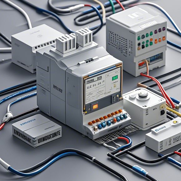
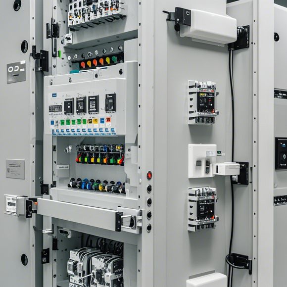
PLC Wiring Diagram and Schematic Analysis for Export Operations
Sure, I'll do my best to summarize your content in a concise and coherent way.---**Export Operations PLC Wiring Diagram & Schematic Analysis**In the realm of manufacturing, export operations are crucial for businesses looking to expand their reach globally. To facilitate smooth operations, it is essential to have an accurate and efficient electrical wiring diagram for the export setup.The PLC (Programmable Logic Controller) is a key component in such setups. A well-designed wiring diagram ensures that all components work together seamlessly, providing a clear roadmap for technicians to follow.Furthermore, schematic analysis is vital to ensure that the PLC system is functioning optimally. It enables us to identify potential issues early on, preventing costly downtime and ensuring that the production line runs smoothly.In conclusion, having a detailed PLC wiring diagram and schematic analysis not only improves efficiency but also ensures safety and reliability in export operations.
In the realm of international trade, understanding the nuances of the product's technical documentation is crucial. The plc (programmable logic controller), often referred to as a 'smart machine', has become a vital tool in the hands of many exporters. This device not only controls the flow of goods but also provides valuable insights into the efficiency and reliability of your operations.
The first step towards ensuring success in this field is having an accurate understanding of the plc's wiring diagram. This diagram, often found on the manufacturer's website or in the product's datasheet, provides a visual representation of how different components interact with one another. By studying this diagram, you can identify potential issues early on and take proactive measures to address them before they escalate into more significant problems.
Furthermore, it's essential to analyze the PLC's schematic, which offers a deeper dive into the system's internal workings. This detailed diagram shows how various components, such as input devices, processing units, and output devices, are connected together. By examining this schematic, you can gain insight into how the PLC handles inputs, processes data, and generates outputs.

When it comes to exporting products using a plc, having a thorough understanding of its wiring diagram and schematic is like having a safety net. It helps you anticipate any potential issues that may arise during the manufacturing process or when installing the PLC in the field. By being well-informed about its functionality, you can minimize downtime and improve overall productivity.
For instance, if you notice that a certain component is not functioning properly, you can quickly identify the problem by referencing the wiring diagram. You might find out that a wire has been disconnected or a switch is not set correctly, leading to a faulty connection between components. With this knowledge at your fingertips, you can take corrective action before it leads to a complete breakdown of the PLC system.
Moreover, analyzing the schematic can help you optimize the PLC's performance. For example, if you discover that some components are operating at high speeds while others are idling, you can adjust the system's settings to balance the load and prevent overheating. This kind of proactive maintenance ensures that the PLC continues to function efficiently even under stressful conditions.
Another advantage of analyzing the wiring diagram and schematic is that it helps you comply with regulations. Many industries have strict guidelines for electrical safety, and understanding how a PLC operates can help you ensure that your products meet these requirements. This can save you from costly fines and reputational damage.
Of course, mastering these technical documents takes time and practice. But with consistent effort and attention to detail, you can become proficient in analyzing the plc's wiring diagram and schematic, becoming a valuable asset in your export business. After all, what good is a successful export operation without reliable machinery and systems? So, let's get cracking and start analyzing!
Content expansion reading:
Content:
Hey there! If you're new to the world of PLCs (Programmable Logic Controllers) or just need a refresher on interpreting those complex wiring diagrams, you've come to the right place. Today, we're diving into the nitty-gritty of PLCs with a focus on deciphering those confusing diagrams by looking at real-life examples. So, grab a cup of coffee, and let's get started!
First things first, what is a PLC wiring diagram? It's a blueprint that shows how all the electrical components of a PLC system are interconnected. This includes the power supply, PLC unit, input devices (like sensors), output devices (like actuators), and any other peripherals. The diagram is essential for ensuring that the system is installed correctly and for troubleshooting when things go wrong.

Now, let's talk about why these diagrams can be so confusing. For starters, they often use a variety of symbols to represent different components, and if you're not familiar with these symbols, the diagram might as well be written in a foreign language. Additionally, the sheer number of wires and connections can be overwhelming, especially for beginners.
But don't worry, we're going to demystify all of this together. To start, let's look at a simple PLC wiring diagram. We've got our PLC unit, some input sensors, and output actuators. The PLC is the brain of the operation, receiving signals from the inputs and controlling the outputs. The inputs might be switches, buttons, or sensors that detect when something happens, like a machine being filled or a door being opened. The outputs, on the other hand, are the devices that the PLC controls, such as motors, lights, or valves.
In the diagram, you'll see lines connecting the PLC to the inputs and outputs. These lines represent the wires that carry the electrical signals. The PLC uses these signals to make decisions and control the system. For example, if a sensor detects a certain condition, the PLC might turn on an alarm or start a motor.
One key thing to remember is that PLC wiring diagrams are typically drawn with power supplies at the top and the PLC at the bottom. Inputs are usually on the left, and outputs are on the right. This makes it easier to follow the flow of the system.
Now, let's look at a more complex diagram with multiple inputs and outputs. This can get pretty intricate, but if you take it step by step, it's not as bad as it seems. Start by identifying the main components: the PLC, power supply, inputs, and outputs. Then, trace the lines to see how they connect. It often helps to color-code your diagram or use a legend to keep track of what each wire does.
When you're working with PLCs in the field, it's crucial to have a good understanding of these diagrams. They'll guide you through installation, help you troubleshoot issues, and even allow you to modify the system if needed. For instance, if a machine isn't responding as it should, you can refer to the diagram to check the wiring and see if there's a loose connection or a faulty sensor.
In conclusion, PLC wiring diagrams are a vital part of any industrial control system. By taking the time to understand these diagrams, you're not only enhancing your skills as a technician but also ensuring the safe and efficient operation of the equipment you work with. So, keep practicing, ask questions when you're stuck, and before you know it, you'll be interpreting these diagrams like a pro!
Articles related to the knowledge points of this article:
PLC Programming for Automation Control in the Manufacturing Industry
How to Use a PLC Controller for Your Business
PLC (Programmable Logic Controller) Control System Basics
The Role of Programmable Logic Controllers (PLCs) in Foreign Trade Operations
Connecting a PLC Controller to Your Computer
PLC Controllers: A Comprehensive Guide to Understanding Their Prices