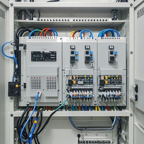
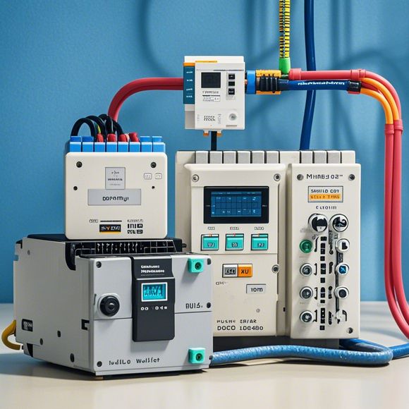
PLC Control System: A Dynamic Overview of Principles and Applications
PLC Control System: A Dynamic Overview of Principles and ApplicationsThe Programmable Logic Controller (PLC) is a crucial component in industrial automation, enabling precise control over various systems. This system uses digital logic to manage and control the flow of power and signals within a plant. It can automate repetitive tasks, monitor process variables, and respond quickly to changes in production conditions. The principles of operation are simple yet powerful, allowing for complex control strategies. PLCs come in various forms, from small devices for simple applications to large-scale systems that can handle massive amounts of data. They are widely used across industries, including manufacturing, healthcare, and energy management. In summary, the PLC Control System provides an essential tool for modern industrial operations, providing reliable and efficient control solutions.
In the world of industrial automation, the role of programmable logic controllers (PLCs) is unparalleled. These versatile devices have revolutionized the way we manage complex processes, from manufacturing to healthcare. At the heart of this revolution lies their ability to control systems with precision and efficiency, making them a critical part of any successful industrial operation.
To begin our discussion on PLCs, let's first delve into the principles that underpin their functionality. PLCs are designed to handle large amounts of data in real-time, making it possible to react quickly to changes in conditions or inputs. This capability stems from their ability to execute instructions stored on chips within the device, rather than relying on external memory systems.
One of the key components of a PLC system is its microprocessor. This central unit acts as the brain of the system, allowing it to process and analyze input signals and output commands to various devices and systems within the plant. The microprocessor can be configured to perform a variety of tasks, such as monitoring temperature, controlling valves, or automating assembly lines.
Another crucial element of a PLC system is its communication network. This network enables the PLC to communicate with other devices and systems within the plant, allowing for seamless coordination between different parts of the system. For example, if the PLC detects a problem with a machine tool, it can communicate this information to the operator via a wireless link, preventing downtime and minimizing costs.

When it comes to programming, PLCs offer a wide range of options for setting up their configurations. This includes using a variety of programming languages, from simple text-based scripts to more complex object-oriented languages like C++ or Python. With the appropriate software tools available, even novice programmers can create custom routines that meet the unique requirements of their particular application.
The advantages of PLCs are numerous. First and foremost, they provide a high degree of flexibility and adaptability, allowing for customized solutions tailored to individual plants. Additionally, they can save significant time and resources by performing repetitive tasks automatically, freeing up operators to focus on more complex and challenging work.
Of course, like any powerful tool, PLCs come with their own set of challenges. One of the main concerns is the risk of errors or misconfigurations leading to unintended outcomes or even catastrophic failures. To mitigate this risk, careful planning and documentation must be put in place before implementing a PLC system, along with regular maintenance checks and updates to ensure that everything is functioning smoothly.
Another important consideration is the need for skilled personnel who can understand and interpret the complex code and algorithms that underlie a PLC system. While some basic programming knowledge may be required, those with advanced skills can take advantage of the power and versatility of these devices, allowing for truly innovative and efficient solutions.
Finally, it's worth noting that PLCs are only one component among many in the world of industrial automation. In fact, many modern systems incorporate a variety of other technologies, such as sensors, actuators, and communication protocols, all working together to create a comprehensive and reliable solution tailored to each specific application. As such, it's crucial for those looking to implement PLC systems to stay up-to-date with the latest advancements and best practices in this rapidly evolving field.
In conclusion, PLCs represent a powerful and flexible solution for managing complex industrial processes. With their ability to execute instructions stored on chips, communicate effectively with other systems, and adapt to changing conditions, they have become an essential part of modern manufacturing and production operations across a wide range of industries. Whether you're a seasoned professional or just starting out, there's always something new to learn about PLCs and how they can help you achieve your goals. So why not take a closer look at what makes these marvels of technology so special?
Content expansion reading:
Content:
Hey there! If you're new to the world of PLCs (Programmable Logic Controllers), or you're looking to brush up on your knowledge, understanding PLC control system wiring diagrams is a crucial step. These diagrams can seem intimidating at first, but once you know what to look for, they're actually pretty straightforward.
So, let's dive in and break down what a PLC control system wiring diagram is and how to interpret it.
First things first, a PLC control system wiring diagram is a visual representation of the electrical connections and components in a PLC system. It shows how the various parts of the system are interconnected, including the PLC itself, input devices, output devices, and any other associated equipment.
When you're looking at a PLC wiring diagram, you'll typically see a few key components:
1、PLC Unit: This is the brain of the system. It's where the programming and logic take place.
2、Input Devices: These are the sensors that provide data to the PLC. They can be switches, buttons, temperature sensors, or any other device that sends a signal to the PLC.
3、Output Devices: These are the devices that receive instructions from the PLC. They can be motors, lights, solenoids, or anything that needs to be controlled by the PLC.
4、Power Supplies: These provide the necessary voltage to the PLC and other components.

5、Relays and Contactors: These are switches that control power in the system.
The diagram will show how these components are connected, with lines representing the electrical connections. It's important to note that the lines in the diagram don't necessarily reflect the physical layout of the equipment; they're more concerned with the logical connections.
Here's a quick rundown of what you might see in a PLC wiring diagram:
Symbols: Each component will be represented by a specific symbol. Make sure you understand what each symbol means.
Lines: The lines between components indicate the flow of electricity or data. A solid line usually means there's a continuous flow, while a dashed line might indicate an alternate or switched path.
Numbers and Letters: These are used to identify specific points in the system. They can help you match up wires and understand the function of different parts.
Terminal Strips: These are where wires are connected to the PLC. The diagram will show which wires go to which terminals.
When you're working with PLC control system wiring diagrams, here are a few tips to keep in mind:
Read the Manual: Always refer to the manufacturer's manual for specific information about the PLC and its components.
Stay Organized: Use a systematic approach when wiring, and keep your work area clean and organized.
Test as You Go: Before you power up the system, test each connection to ensure it's correct.
Documentation: Keep thorough documentation of your wiring, in case you need to make changes or troubleshoot in the future.
Remember, safety is paramount when working with electrical systems. Always follow proper safety procedures and consult with a professional if you're unsure about anything.
By understanding PLC control system wiring diagrams, you'll be better equipped to maintain, troubleshoot, and improve these systems. So, take your time, study the diagrams, and soon you'll be reading them like a pro!
Articles related to the knowledge points of this article:
Mastering the Art of Plc Controllers: A Comprehensive Guide to Understand and Implement
PLC Programming for Automation Control in the Manufacturing Industry
How to Use a PLC Controller for Your Business