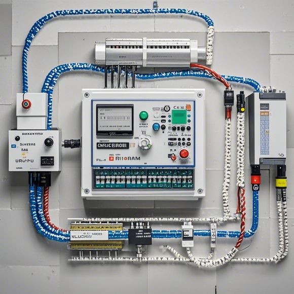
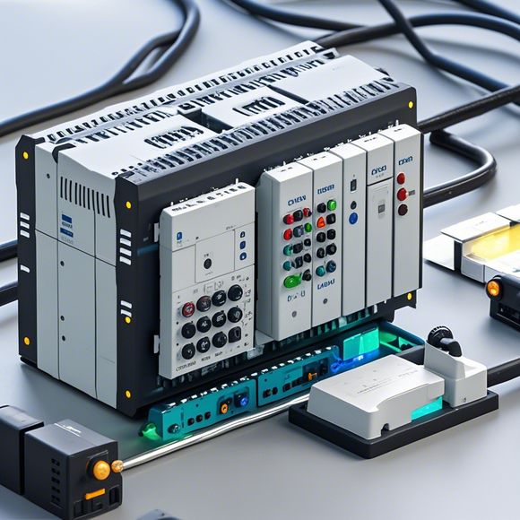
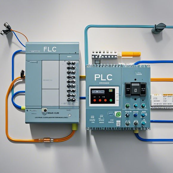
plc控制器接线图
Title: PLC Controller Wire DiagramWhen it comes to industrial automation, the Programmable Logic Controller (PLC) is often a critical component. The wire diagram of an PLC controller not only shows the connections between various components but also provides a clear guide for troubleshooting and maintenance. Here is a summary of the key elements involved in a typical PLC controller wiring diagram:1. **Input Units**: These consist of switches, sensors, and other input devices that detect external conditions and trigger actions within the system. For instance, a push button or a temperature sensor can be included as input units.2. **Output Units**: These are responsible for controlling the output of the system, such as actuators like motors or valves. They include relays, contactors, and solenoids.3. **Analog Signal Units**: These units handle analog signals from sensors and convert them into digital format for processing by the PLC. Examples could include potentiometers or transducers.4. **Communication Units**: To ensure smooth communication between the PLC and other systems, communication modules are essential. They might be used for interfacing with other computers or external devices.5. **Power Sources and Ground**: Power cables and a grounding system must be correctly connected to supply power to the PLC and maintain safety.6. **Safety Measures**: In addition to electrical safety, ensuring that all inputs and outputs are properly protected against voltage drops and short circuits is crucial for the safe operation of the PLC.7. **Testing and Maintenance**: After the wiring diagram is complete, it is important to perform tests to ensure that each unit works properly. This includes checking for proper connection points and confirming that no unnecessary loops exist.The wire diagram of a PLC controller plays a significant role in ensuring the reliable execution of industrial tasks. By understanding these basic components, you will be well-prepared to handle any potential issues during the design and implementation phases of your projects.
"PLC Controller Wiring Diagram: A Step-by-Step Guide to Understanding and Troubleshooting Electrical Systems"
Hey everyone, today I'm going to take you on a journey through the world of PLC controllers, where we'll unravel the intricacies of their wiring diagrams. So, let's dive right into it!
Firstly, when dealing with any electrical system, understanding its components is key. In the case of PLC controllers, that means getting a grasp of their internal workings, how they communicate with each other, and how they affect the overall functioning of your machinery.
Now, let's talk about the wiring diagram. It's like a road map for your PLC controller, showing you exactly where each wire comes from and goes to. But don't worry, it's not as complicated as it might seem at first glance.

To start with, let's take a look at some common elements found in most PLC controllers. There's the Central Processing Unit (CPU), which is the brain of the machine; the Power Supply Unit (PSU), responsible for providing power to everything; and the input/output modules (I/O modules), where sensors, actuators, and other devices connect.
Now, let's focus our attention on the wiring diagram itself. It usually consists of two parts: the top part, which shows the connections between the different modules and components; and the bottom part, which details the connections between these modules.
So, what does each part do? Well, the top part is where you'll see labels indicating the names of the modules, along with arrows pointing to where each wire connects. This helps you understand the flow of power and data within your PLC controller.
On the bottom part, you'll find more detailed information, including pin numbers and colors for each wire. This can get a bit overwhelming at first, but trust me, it gets easier once you get the hang of it.
Now, let's talk about troubleshooting. If something goes wrong with your PLC controller, chances are there's an issue with its wiring diagram. To fix it, you'll need to identify the problem area first. For example, if your motor isn't turning on, you could try checking the connections between the motor control module and the PSU.
Another thing to keep in mind is safety. When working with electricity, it's essential to follow proper guidelines and procedures. Make sure to wear gloves, eye protection, and other necessary safety gear, and never work on an energized circuit.
In conclusion, by now, you should have a good understanding of how PLC controllers work and how to troubleshoot them using their wiring diagrams. Remember, practice makes perfect – so go ahead and experiment with your own PLC controllers to become a master electrician!
Content expansion reading:
Content:

Hey there! If you're new to the world of PLCs (Programmable Logic Controllers), or you're just looking to brush up on your knowledge, understanding PLC controller wiring diagrams is a crucial step. These diagrams can seem intimidating at first, but once you know what to look for, they're actually pretty straightforward.
So, let's dive in and break down what a PLC controller wiring diagram is and how to interpret it.
First things first, a PLC controller wiring diagram is a visual representation of the electrical connections between the various components of a PLC system. It shows you how the PLC is connected to input devices (like sensors), output devices (like actuators), and other peripheral equipment. The diagram is designed to help you understand the flow of information and power within the system.
When you're looking at a PLC controller wiring diagram, you'll typically see a few key elements:
1、PLC Module: This is the heart of the system. It's where all the programming and logic happen.
2、Input Devices: These are the things that provide data to the PLC, like limit switches, sensors, or push buttons.
3、Output Devices: These are the things that the PLC controls, like motors, lights, or solenoids.
4、Power Supplies: These provide the necessary voltage to the PLC and other components.
5、Relay Contacts: These are used to control higher power loads.

6、Wires: These connect all the components together.
Each component is represented by a symbol, and the wires are represented by lines with arrows that indicate the direction of the electrical signal. The wires are usually color-coded to help with identification.
Here's a simple example of what a PLC controller wiring diagram might look like:
PLC Module
|
v
Input Devices (e.g., Sensors)
|
v
Output Devices (e.g., Actuators)
|
v
Power Supply
|
v
Relay Contacts
In this diagram, the PLC module is connected to input devices, which are then connected to output devices. The power supply provides power to the entire system, and the relay contacts are used to control high-power devices.
When interpreting a wiring diagram, it's important to understand the symbols and the color-coding of the wires. For example, a red wire might indicate a power wire, while a blue wire might be a control wire.
Remember, safety is paramount when working with PLCs and electrical systems. Always ensure that the power is off before making any connections, and never assume that a wire is not live. Double-check your diagrams and consult with a professional if you're unsure about anything.
That's it for a quick overview of PLC controller wiring diagrams. Hopefully, this has given you a better understanding of what these diagrams are and how to read them. If you're looking to get into more detail or need to understand a specific PLC system, there are plenty of resources available online and through technical manuals.
Articles related to the knowledge points of this article:
PLC Controller Wiring Guideline
PLC Controller for Manufacturing Automation
PLC Programming for Automation Control in the Manufacturing Industry