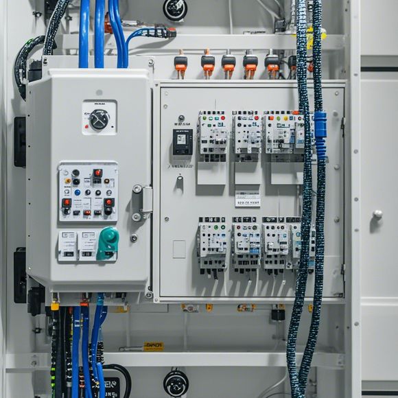
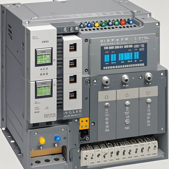
plc控制器接线图
The Plc Controller Wiring Diagram,A Comprehensive GuideThe plc controller, also known as the programmable logic controller, plays a crucial role in the industrial automation field. Its wiring diagram is an essential document that depicts the connections between components and their corresponding functions. In this guide, we will delve into the details of how to create an accurate Plc wiring diagram.Firstly, it is important to understand the basic components involved in a Plc controller. These include the CPU, input/output modules, memory, communication modules, etc. The wiring diagram should clearly show where each component is placed and its corresponding function. It's crucial to follow the manufacturer's instructions and ensure that each connection is correctly labeled.Secondly, the wiring diagram must be visually clear and easy to read. Each signal unit, such as I/O units or analog signal modules, should have a distinct color code to differentiate them from each other. This not only makes the diagram more organized but also helps in diagnosing issues quickly.Moreover, the wiring diagram should be designed with consideration for future expansion or modification. For example, if the system requires adding new devices or features, the diagram should reflect these changes without causing confusion.Lastly, it's vital to ensure that all electrical safety measures are followed during the wiring process. Proper grounding and overvoltage protection should be included to prevent potential hazards.In conclusion, creating a reliable Plc controller wiring diagram requires thorough planning and execution. By following the steps outlined above, you can ensure that your wiring is both functional and safe, enabling your automation systems to run smoothly for years to come.
"Mastering the Art of PLC Controller Wiring - A Comprehensive Guide for Your Next Successful Project"
Introduction:
Hello, everyone! I'm thrilled to be here today to share with you all my expertise on PLC controller wiring. As an experienced and passionate trader in the world of electronics and automation, I am always eager to explore new challenges and expand my knowledge. And when it comes to PLC controller wiring, there is no shortage of opportunities to learn and grow. So without further ado, let's dive right into this fascinating topic together.
Firstly, let's talk about what a PLC (Programmable Logic Controller) is. In simple terms, a PLC is a powerful computer system that can be programmed to perform various tasks based on pre-defined logic. It's like a miniature computer that can handle complex calculations and control systems, making it ideal for industrial environments.

Now, let's discuss the importance of wiring in PLC controllers. When it comes to connecting components such as sensors, actuators, and other devices, proper wiring is crucial for ensuring smooth operation and preventing potential hazards. A well-wired system can provide reliable results, reduce downtime, and improve overall efficiency.
In this guide, we'll delve deep into the art of PLC controller wiring by covering various aspects such as the basics of circuit diagrams, common types of wiring methods, troubleshooting tips, and best practices for achieving optimal results. By the end of this guide, you should have a solid understanding of how to tackle even the most challenging wiring projects.
So, let's start by discussing the basics of circuit diagrams and their role in PLC controller wiring. Circuit diagrams are essential tools that help us visualize and understand the connections between different components in a system. They provide a clear representation of the electrical path that runs from one device to another, helping us identify potential issues and make informed decisions during the wiring process.
When creating a circuit diagram for an PLC controller, it's important to pay attention to the following points:
1、Choose a suitable schematic symbol library or software tool to create the diagram. There are many options available online and on the market that can help simplify the process.
2、Use accurate measurements and dimensions to depict the physical size of components and wires. This will ensure that the wiring is done accurately and efficiently.
3、Include all necessary symbols and components in the diagram, including sensors, actuators, motors, relays, switches, and so on. This will help us quickly find the correct connection point during the wiring process.
4、Pay close attention to the color coding used in the diagram, which typically indicates the polarity of each wire (red = live, black = earth). This will help us avoid shorting or damaging any components while working on the project.
5、Use appropriate labels and descriptions to clearly indicate the function of each component and its position in the system. This will make it easier for others to understand the wiring scheme and assist in troubleshooting if necessary.
Now, onto the main topic of this guide - common types of wiring methods and their applications. There are several ways to connect components in an PLC controller system, each with its own advantages and disadvantages. Here are some of the most common types of wiring methods:
1、Direct wiring: This method involves connecting all components directly using wires and terminal blocks. The advantage of this approach is that it provides a clean and simple way to connect components, making it easy to test and troubleshoot. However, it requires more time and effort to install and may not be suitable for large-scale projects.
2、Through-hole wiring: This method involves drilling holes in the board and installing wires through these holes using screws or bolts. It offers flexibility in terms of installation and assembly but may require additional tools and equipment for larger components.
3、Ceramic capacitors and ferrite beads: These are commonly used in power distribution systems to reduce EMI (Electromagnetic Interference) and improve signal integrity. When wiring components, it's important to consider the impact of these materials on the overall performance of your system.

4、Power distribution: When dealing with high-power components such as motors or fans, it's important to use proper power distribution techniques to ensure safe and efficient operation. This includes using appropriate voltage regulators, fuses, and other safety devices to prevent damage to sensitive components.
Now, onto some practical tips for troubleshooting common issues with PLC controller wiring projects. No matter how well-planned a project may be, problems do arise during execution. Here are some tips to help you navigate these challenges:
1、Check for loose or damaged wires: Loose or damaged wires can lead to short circuits, overheating, or even fire hazards. Always inspect the wires carefully before proceeding with any wiring task.
2、Ensure proper grounding: Grounding is critical for preventing electrocution and protecting against electrical surges. Make sure that all exposed wires are properly connected to a grounding point on the PLC controller or other relevant components.
3、Test each component individually: Before connecting them together, test each component separately to ensure that they are functioning correctly. This will help catch any issues early on and minimize downtime caused by faulty components.
4、Use proper tools and techniques: Using the right tools and techniques is essential for completing PLC controller wiring projects successfully. Invest in quality tools such as wire cutters, crimpers, soldering irons, and connectors to ensure accuracy and reliability.
Finally, let's discuss some best practices for achieving optimal results when wiring PLC controllers. Following these guidelines will help you avoid common mistakes and improve the overall performance of your system. Here are some key points to keep in mind:
1、Keep everything organized: Keep your work area tidy and organized to facilitate easy access to components and tools. This will save time and prevent errors during the wiring process.
2、Follow the manufacturer's instructions: Each PLC controller has specific requirements for wiring and installation. Always refer to the manufacturer's documentation or contact technical support if needed before starting a project.
3、Use appropriate cable types: Different types of cables are designed for different applications and purposes. Choose the right cable type for your project based on factors such as length, temperature range, and electrical requirements.
4、Consider adding protection features: Adding additional protection features such as fuses, circuit breakers, or surge protectors can help mitigate potential risks associated with your wiring project.
5、Test thoroughly before finalizing the installation: Before finalizing the installation of your wiring project, conduct thorough testing to ensure that everything functions properly and operates smoothly throughout the entire system.
In conclusion, PLC controller wiring is a complex but rewarding process that demands careful attention to detail. By following the tips and best practices outlined in this guide, you can ensure that your next PLC controller wiring project will be completed successfully and safely. Remember, with practice and experience, anyone can become an expert at handling PLC controller wiring challenges. So get ready to embark on this exciting journey of mastering the art of PLC controller wiring!

Content expansion reading:
Content:
Hey there! If you're new to the world of PLCs (Programmable Logic Controllers), or you're just looking to brush up on your knowledge, understanding PLC controller wiring diagrams is a crucial step. These diagrams can seem intimidating at first, but once you know what to look for, they're actually pretty straightforward.
So, what exactly is a PLC controller wiring diagram? It's a visual representation of the electrical connections between the various components of a PLC system. This includes the power supply, the PLC itself, input devices (like sensors), output devices (like actuators), and any other peripherals.
The first thing you'll notice on a PLC wiring diagram is a set of symbols. Each symbol represents a different component or connection type. For example, you'll see symbols for the PLC, relays, timers, switches, and more. It's important to familiarize yourself with these symbols because they're the key to understanding the diagram.
Next, you'll see lines connecting these symbols. These lines represent the electrical paths between the components. They can indicate power lines, control signals, or data connections. Different colors are often used to denote different types of signals, so keep an eye out for that.
Power supply is a critical part of the diagram. You'll see how the AC or DC power is connected to the PLC and how it's distributed to other components. Always pay attention to the voltage and amperage ratings to ensure you're not overloading any part of the system.
Inputs and outputs are another essential part of the diagram. Inputs show how devices like sensors or switches are connected to the PLC. Outputs show how the PLC controls devices like motors, lights, or other control systems. Each input and output has a specific address or identifier within the PLC, which is also shown on the diagram.
When you're looking at a PLC controller wiring diagram, it's also important to consider the physical layout of the components. The diagram should reflect the actual placement of devices in the control panel or on the factory floor. This helps with troubleshooting and maintenance.
If you're working with a complex system, the wiring diagram might include additional details like control circuits, protective devices (like fuses and circuit breakers), and grounding schemes. These are all crucial for ensuring the safe and proper operation of the PLC system.
Remember, PLC controller wiring diagrams are not just for show; they're a vital tool for planning, installation, operation, and maintenance. Always refer to the manufacturer's documentation and safety guidelines when working with PLC systems. And if you're ever in doubt, consult with a professional.
So there you have it! With a bit of practice and a good understanding of the symbols and terminology, you'll be able to read and interpret PLC controller wiring diagrams like a pro. Happy wiring!
Articles related to the knowledge points of this article:
PLC Controller Selection Guide for Foreign Trade Operations
PLC Controller Wiring Guideline
PLC Programming for Automation Control in the Manufacturing Industry
How to Use a PLC Controller for Your Business
PLC (Programmable Logic Controller) Control System Basics
Plumbers Rule! The Role of PLC Controllers in the World of Waterworks