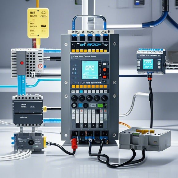
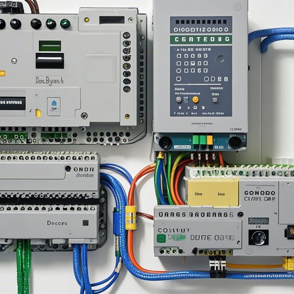
PLC Controller Wiring Diagram Guide - An Overview
This guide provides a detailed overview of the wiring diagram for PLC controllers. It explains each component, from the main board to the various sensors and actuators, and how they are connected together to form a complete system for controlling industrial processes. The guide also covers important considerations such as safety standards and electrical connections, ensuring that readers can confidently install and maintain their own PLC systems. Whether you're a professional engineer or a hobbyist, this guide will provide you with the knowledge you need to get started.
As a forward-thinking trader and strategist, it is essential to have a comprehensive understanding of the intricacies involved in the process of wiring a Plc (Programmable Logic Controller) controller. This guide aims to provide a detailed overview of the steps involved in connecting the components of a Plc controller, from the initial setup to final testing, ensuring that every aspect is covered.
Firstly, let's delve into the importance of a well-maintained Plc controller. A Plc controller is a crucial tool for any industrial operation, as it can automate complex processes and improve efficiency. However, maintaining its functionality requires regular monitoring and troubleshooting. Therefore, understanding the various components of a Plc controller and their roles is essential for effective maintenance.
Next, let's examine the basic components of a Plc controller. These include the CPU, which is the brain of the controller; the input/output modules, which handle communication with external devices; and the program memory or ROM, which stores the instructions for the controller. Each component plays a vital role in ensuring the controller functions optimally.
Now, let's discuss the wiring diagram. The wiring diagram is a visual representation of the connections between different components of the Plc controller. It provides a clear understanding of how each part interacts with each other to function properly. By studying the wiring diagram, we can identify potential issues that may arise during installation or maintenance, enabling us to address them promptly.

When it comes to connecting the components of the Plc controller, there are several steps to follow. Firstly, ensure that the power supply is stable and compatible with the controller. Next, connect the input/output modules to the appropriate ports on the controller. Then, connect the program memory or ROM to the controller through a data bus. Finally, test the connection by powering up the controller and verifying that all components are working correctly.
In addition to the technical aspects, it is also important to consider safety considerations when wiring a Plc controller. Make sure that all connections are made securely, and avoid using exposed wires or loose connections that may cause hazardous situations. Also, be aware of the potential risks associated with electrical surges and overheating.
Another important aspect is the testing process. After completing the wiring, it is essential to perform tests to ensure that the controller functions properly. Test the connections by powering up the controller and verifying that all components are responding as expected. If any issues are detected, address them immediately to prevent further problems.
Finally, it is crucial to regularly update the program stored in the program memory or ROM. This ensures that the controller continues to function optimally and is compatible with new technologies and applications.
In conclusion, wiring a Plc controller is a complex but rewarding process that requires careful planning and execution. With proper understanding of the components and the wiring diagram, along with safety precautions and testing, we can achieve efficient and reliable automation solutions for our industrial operations. Remember to stay updated with the latest trends and technologies to maintain the best performance from our Plc controllers.
Content expansion reading:
Content:
Hey there! If you're new to the world of PLCs (Programmable Logic Controllers), or you're just looking to brush up on your knowledge, understanding PLC controller wiring diagrams is a crucial step. These diagrams can seem intimidating at first, but once you know what to look for, they're actually pretty straightforward. In this post, we'll break down the basics of PLC wiring diagrams and help you interpret them with ease.
First things first, let's talk about what a PLC controller wiring diagram is. It's a visual representation of the electrical connections between the various components of a PLC system. This includes the power supply, the PLC itself, input devices (like sensors), output devices (like actuators), and any other peripherals. The diagram is designed to show you how all these parts are connected and how they interact with each other.
When you're looking at a PLC controller wiring diagram, you'll typically see a few key elements:
1、Power Supply: This is where the electrical power comes from to run the PLC and its connected devices. You'll see lines indicating the power input (usually 24V DC) and how it's distributed.
2、PLC Chassis: This is the main body of the PLC, where all the internal components are housed. The wiring diagram will show how the power is connected to the PLC and how the I/O (Input/Output) modules are connected to the chassis.
3、Input Devices: These are the sensors or switches that provide data to the PLC. They're usually represented by symbols for different types of sensors (like limit switches, proximity sensors, or temperature sensors) and are connected to the PLC's input modules.

4、Output Devices: These are the actuators or devices that the PLC controls. They're connected to the PLC's output modules and can include things like motors, valves, or lights.
5、Other Components: Depending on the complexity of the system, you might see other components like relays, transformers, or safety devices.
To interpret a PLC controller wiring diagram, you'll want to follow these steps:
- Identify the power supply and understand how it connects to the PLC.
- Locate the PLC chassis and note how the I/O modules are connected to it.
- Find the input devices and understand how they're wired to the PLC's input modules.
- Look for the output devices and see how they're connected to the PLC's output modules.
- Check for any additional components and how they fit into the overall system.
Remember, PLC wiring diagrams are like blueprints for your control system. They're essential for troubleshooting, maintenance, and understanding how your system works. So take the time to study them, and you'll be able to navigate the world of PLCs with confidence.
If you're new to PLCs, don't worry! There are plenty of resources available to help you learn. From online courses to technical manuals, there's a wealth of information out there to get you up to speed. And if you ever get stuck, don't hesitate to reach out to more experienced colleagues or professionals for assistance.
Understanding PLC controller wiring diagrams is a skill that will serve you well in the world of automation. So grab a diagram, take a deep breath, and start exploring!
Articles related to the knowledge points of this article:
PLC Controller Selection Guide for Foreign Trade Operations
Mastering the Art of Plc Controllers: A Comprehensive Guide to Understand and Implement
PLC Controller Wiring Guideline