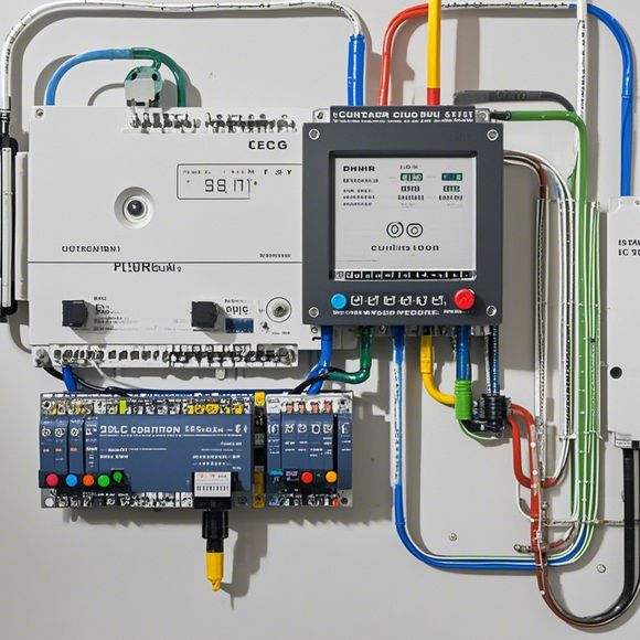
PLC Input and Output (I/O) Wiring Diagrams for Foreign Trade Operations
Sure, here is a summary of your content in concise and clear English:Foreign trade operations involve the use of ProgrammableLogicControllers (PLCs) for automation and control. In this context, I/O Wiring Diagrams are used to depict the connections between various components such as sensors, actuators, and control modules. These diagrams are crucial for ensuring that the PLC operates as intended and provides reliable feedback for making informed decisions during foreign trade operations. The wiring diagrams should include all necessary details such as the types of wires used, their lengths, and the connections between various components. Additionally, they should be designed to meet the specific requirements of the foreign trade operation, including safety and compliance with regulatory standards. Overall, I/O Wiring Diagrams are an essential part of the foreign trade automation process and play a critical role in ensuring smooth operations and successful trade transactions.
As an experienced trader in the global marketplace, understanding the complexities of international trade can be challenging. One crucial aspect that needs careful attention is the accurate wiring of PLC inputs and outputs (I/O). In this guide, we will delve into the essential aspects of PLC I/O wiring diagrams for foreign trade operations.

At the heart of any successful foreign trade operation lies the ability to accurately read and interpret data from sensors, actuators, and other devices. This requires a clear understanding of how these devices communicate with each other using PLC inputs and outputs. A well-designed PLC I/O wiring diagram is the foundation upon which all foreign trade activities are built, ensuring that communication between different parts of the system is seamless and efficient.
Firstly, when working with PLC I/O wiring diagrams, it is essential to understand the basic components involved. These include input devices, output devices, and control logic. The input devices capture data from various sources such as sensors and actuators, while output devices send signals to various devices such as motors or switches to control the flow of goods. Control logic is responsible for interpreting the input data and generating appropriate output signals based on predefined rules.
Now, let's take a closer look at some of the key considerations when creating an effective PLC I/O wiring diagram for foreign trade.
One of the primary concerns when designing a PLC I/O wiring diagram for a foreign trade scenario is ensuring compatibility. Different countries have their own standards and regulations regarding electrical and electronic equipment, which must be adhered to in order to ensure safe and reliable operation. It is important to consult with local experts and regulatory bodies to determine what type of PLC and its associated I/O components are suitable for the specific trade environment.
Another critical aspect of PLC I/O wiring diagrams is the placement of devices. Proper positioning of input and output devices is essential for optimal communication between them. For example, if a device is located far from the control panel, it may require longer cables or additional relays to connect it to the control panel. Additionally, proper placement of devices can minimize interference and improve signal transmission efficiency.
In order to ensure maximum efficiency and reliability, it is important to consider the power requirements for each device. Different devices require varying amounts of power, and not all devices can be powered by the same source. Therefore, a thorough analysis of each device's power requirements and potential sources of power is necessary to design a reliable and cost-effective power supply system.
Finally, it should be noted that PLC I/O wiring diagrams must also account for safety considerations. Ensuring that all electrical components meet the highest safety standards and following proper electrical installation practices can prevent fire hazards, electrocution, and other accidents. Additionally, regular maintenance and testing of the wiring system can help identify and fix any potential issues before they become more serious problems.
In conclusion, creating an effective PLC I/O wiring diagram for foreign trade operations requires careful consideration of various factors, including compatibility, device placement, power requirements, and safety. By following best practices and utilizing the knowledge gained from experts and regulatory bodies, businesses can streamline their foreign trade operations and optimize their performance while maintaining high levels of safety and security.
Content expansion reading:
Content:

Hey there! If you're new to the world of PLCs (Programmable Logic Controllers), one of the first things you'll need to wrap your head around is how to interpret those complex input/output wiring diagrams. Don't worry, it's not as daunting as it seems! Let's break it down in a way that's easy to understand.
First things first, what is a PLC input/output (I/O) wiring diagram? It's a blueprint that shows how the various inputs and outputs of a PLC are connected to other devices, sensors, and actuators in a control system. Inputs are the pathways through which the PLC receives data or signals from the environment, while outputs are the pathways through which the PLC sends signals to control other devices.
When you're looking at a PLC I/O wiring diagram, you'll typically see a bunch of symbols representing different types of I/O. For example, you might see symbols for switches, sensors, motors, and more. Each of these symbols will have a corresponding number or letter that tells you which PLC input or output it's connected to.
Let's talk about inputs. These are usually represented by a circle or a square with a line coming out of it. The line might have a number or a letter next to it, which corresponds to the PLC input channel. When the input device, like a switch or a sensor, changes state (opens or closes), it sends a signal to the PLC through this input channel.
Outputs, on the other hand, are represented by a similar shape but with a line going into it. This line will also have a number or letter that corresponds to the PLC output channel. When the PLC decides to do something based on the program it's running, it will send a signal out through an output channel to an output device, like a motor or a solenoid.
To make sense of all this, you need to understand the symbology used in the diagram. Different manufacturers may have slightly different symbols, so it's important to refer to the documentation that comes with the PLC or the control system.
Now, let's talk about the different types of inputs and outputs you might see. Digital inputs and outputs are the simplest. They're either on or off, represented by 1 or 0 in the PLC program. Analog inputs and outputs, on the other hand, can represent a continuous range of values, like temperature or pressure.
When you're working with a PLC, it's also important to understand the concept of racks and modules. A PLC rack is like a frame that holds various modules, including I/O modules. These modules are what actually connect to the input and output devices.
To sum it up, understanding PLC I/O wiring diagrams is all about learning the language of the symbols and how they relate to the inputs and outputs of the PLC. With a bit of practice, you'll be able to read these diagrams like a pro and effectively troubleshoot any issues that come up in your control system.
Articles related to the knowledge points of this article:
Smart Manufacturing Solutions with PLC Integrated Machinery
PLC Controller for Manufacturing Automation
The cost of a PLC Controller: A Comprehensive Analysis
PLC (Programmable Logic Controller) Control System Basics
Plumbers Rule! The Role of PLC Controllers in the World of Waterworks