plc控制器接线图
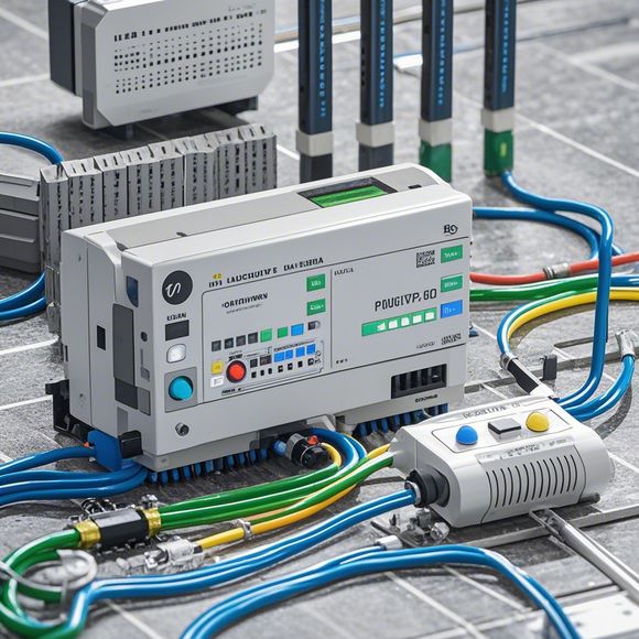
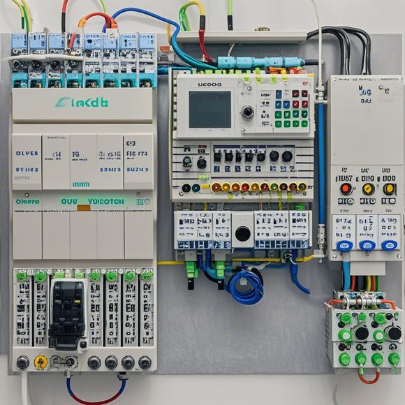
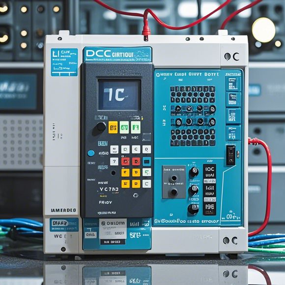
The Plc Controller Wiring Diagram is a detailed representation of how the various hardware components are interconnected within a control system. This includes not only the physical connections between components but also how these connections are designed to ensure efficient and effective communication between them. The wiring diagram serves as the foundation upon which the overall functioning of the PLC controller is based, providing a clear visual representation of the electrical pathways that allow commands to be processed and responses to be generated in real time.In the context of modern industrial automation, the importance of accurate and reliable wiring cannot be overstated. The wiring diagram not only ensures that each component performs its intended task but also facilitates troubleshooting and maintenance, minimizing downtime and maximizing efficiency. It is this level of detail and precision that makes the wiring diagram a crucial component of any PLC controller's functionality.As one delves deeper into the world of industrial control systems, it becomes evident that the wiring diagram forms the backbone of many complex operations. From simple factory automation to advanced robotics, the ability to understand and interpret the wiring diagram is essential for ensuring that machinery operates at peak performance levels.Furthermore, the wiring diagram is more than just a technical document; it is a visual representation of the system's architecture and design philosophy. It allows engineers and technicians to visualize the flow of data and information within the system, making it easier to identify potential issues and suggest improvements.In conclusion, the PLC controller wiring diagram is more than just a series of lines and connections; it is a vital tool for maintaining and operating industrial equipment. Its precise representation of the system's architecture ensures that every step of the manufacturing process runs with precision and efficiency, from the smallest assembly line to the most sophisticated production facility.
"Mastering the Art of PLC (Programmable Logic Controller) Connection: A Guide for Success"

Content:
As an experienced trader in international markets, it's crucial to stay up-to-date with the latest trends and best practices when dealing with Programmable Logic Controllers. Whether you're a small-business owner or a seasoned industry professional, mastering the art of PLC connection is essential for ensuring smooth operations. In this guide, we'll delve into the intricate world of PLCs and provide insights into their significance in today's global economy.
Firstly, let's talk about the importance of PLCs in modern manufacturing. These intelligent controllers are at the heart of automation technology, enabling companies to streamline production processes and reduce downtime. By integrating PLCs into your supply chain, you can increase efficiency, minimize waste, and meet stringent regulatory requirements. Moreover, PLCs can automate complex tasks such as feeding machinery, monitoring sensor data, and managing inventory levels, all while providing real-time insights into operational performance.
Now, let's discuss the technical aspects of connecting PLCs. When working with these devices, it's essential to have a solid understanding of their programming language—a topic that may seem daunting to some. However, by following a few simple guidelines, you can quickly become comfortable with coding and developing programs that work seamlessly with PLCs. For instance, one common programming language used for PLC applications is Ladder Diagram Language (LDL). This language offers a visual approach to creating flowcharts and logic diagrams, making it easier to understand and implement complex algorithms. Additionally, there are other languages such as Function Block Diagram (FBD), which allows programmers to define functions within individual modules and connect them together.
Another crucial aspect of PLC connection involves selecting the right hardware components. Depending on your needs, there are various types of PLCs available, including AC drives, DC drives, and hybrid systems. It's important to choose a model that fits your production line's size and complexity. Additionally, you should consider factors like compatibility, power capacity, and connectivity options when selecting hardware. Once you have the right components, it's time to install and configure them properly. This includes setting up wiring schematics, installing relays and switches, and configuring the PLC's settings.
In terms of troubleshooting PLC connections, it's essential to have a basic knowledge of common issues and solutions. Some common problems include communication errors, software glitches, and hardware failures. To resolve these issues, you can refer to the manufacturer's documentation or seek expert advice from a qualified technician. Additionally, staying informed about the latest developments in PLC technology can help you identify potential issues early on and take proactive measures to address them.
Finally, let's discuss the benefits of investing in PLCs for businesses. These devices offer a cost-effective solution for streamlining production processes and increasing efficiency. They also enable businesses to operate more reliably and securely, reducing downtime and minimizing risks. Moreover, by adopting PLC technology, you can tap into new markets and expand your reach. With the right tools and expertise, you can create innovative solutions that set you apart from your competitors.

In conclusion, mastering the art of PLC connection is essential for any business looking to improve its efficiency and competitiveness. By following best practices for programming, selecting the right hardware components, troubleshooting issues, and exploring the benefits of PLC technology, you can unlock the full potential of PLCs and drive growth in your industry. Remember, success comes from taking ownership of your operations and investing in the future of your business.
Content expansion reading:
Content:
Hey there! If you're new to the world of PLCs (Programmable Logic Controllers), or you're just looking to brush up on your knowledge, understanding PLC controller wiring diagrams is a crucial step. These diagrams can seem intimidating at first, but once you know what to look for, they're actually pretty straightforward.
So, what exactly is a PLC controller wiring diagram? It's a visual representation of the electrical connections between the various components of a PLC system. This includes the power supply, input devices, output devices, and the PLC itself. The diagram shows you how these components are connected and how they interact with each other.
When you're looking at a PLC controller wiring diagram, the first thing you'll notice is that it's divided into different sections. The power supply section is usually at the top, followed by the input devices, the PLC, and finally, the output devices. Each section is labeled clearly, so you can easily identify what's what.
Input devices are the sensors that provide data to the PLC. They can be switches, buttons, temperature sensors, or any other device that sends a signal to the PLC. Output devices, on the other hand, are the ones that receive signals from the PLC and perform an action. These can be motors, lights, solenoids, or anything that needs to be controlled by the PLC.

The PLC itself is the brain of the system. It's where the programming takes place, and it's responsible for interpreting the input signals and deciding what to do with them. The PLC will then send output signals to the appropriate devices to control the process.
Now, let's talk about the symbols you'll see in a PLC controller wiring diagram. Each component has a specific symbol that represents it. For example, a switch might be represented by a simple line with a circle on the end, while a motor might be a rectangle with a curved line on the top. It's important to understand these symbols so you can interpret the diagram correctly.
In addition to the symbols, you'll also see numbers and letters next to the components. These are known as tags or addresses, and they're used to identify each component within the PLC program. When you're wiring up the system, you'll use these tags to ensure that each component is connected to the right input or output on the PLC.
One of the most important things to remember when working with PLC controller wiring diagrams is that safety is paramount. Always ensure that the power is off before you start working on any wiring, and never assume that a wire is not live. Always test before you touch.
Another tip is to take your time and double-check your work. It's better to find a mistake on the diagram before you've finished wiring everything up than to have to start all over again. And if you're ever in doubt, consult with a more experienced colleague or refer to the manufacturer's manual for guidance.
In conclusion, PLC controller wiring diagrams are a vital tool for anyone working with PLC systems. By understanding the symbols, components, and safety protocols, you'll be able to interpret these diagrams with ease and ensure that your PLC system is wired up correctly. Remember, practice makes perfect, so don't be discouraged if it takes a few tries to get the hang of it. With a bit of time and patience, you'll be reading these diagrams like a pro!
Articles related to the knowledge points of this article:
PLC Programming for Automation Control in the Manufacturing Industry
How to Use a PLC Controller for Your Business
PLC (Programmable Logic Controller) Control System Basics
Plumbers Rule! The Role of PLC Controllers in the World of Waterworks
The Role of Programmable Logic Controllers (PLCs) in Foreign Trade Operations
PLC Controllers: A Comprehensive Guide to Understanding Their Prices