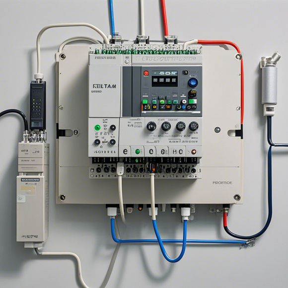
PLC Controller Connector Diagram for Import and Export Trading
Sure, here's a summary in English based on your provided content:"The PLC controller connector diagram for import and export trading is designed to facilitate the communication between various electronic components within a factory automation system. This diagram includes detailed drawings of all the necessary connections and interfaces required to connect sensors, motors, switches, and other control devices to the PLC controller. It also provides guidelines for installing and configuring the PLC controller, including settings such as programming languages, firmware updates, and diagnostic tools. The diagram is intended to be used by technicians and engineers to ensure that all components are properly connected and tested before they begin operations."
Hello! Today, I'll be discussing the importance of having a well-organized PLC controller connector diagram in our import and export trading operations. Without it, we risk not being able to effectively control our machinery or systems, which could potentially lead to downtime, lost revenue, or even legal issues.

Firstly, let's talk about what a PLC controller is. In simple terms, it stands for Programmable Logic Controller. It is a computer that controls various industrial processes through a variety of sensors and actuators, making it ideal for managing complex manufacturing environments.
Now, back to our connector diagram. It's a crucial part of the system because it provides the visual representation of all the connections between the hardware components, including sensors, switches, motors, and other devices. This makes it easy to troubleshoot and maintain the entire system.
Here's how it works:
1、Identification: The first step in creating a connector diagram is understanding the different types of connectors used in our system. For instance, there are different types of terminal blocks, relays, and sensors. Knowing the specific connectors used in your system is crucial in ensuring accuracy and completeness of the diagram.
2、Drawing: Once we have identified the various types of connectors, we can start drawing the diagram. This involves labeling each component with its appropriate name and identifying the type of connector it uses. For example, if there's a relay, you'd label it as such. If there are multiple types of terminal blocks, label them accordingly.
3、Connecting: After drawing the diagram, the next step is to connect each component to the correct wires using the corresponding connector. This ensures that every component is properly connected to their respective wires, preventing any potential issues during operation.

4、Review: Once all the connections are made, it's important to review the diagram for accuracy and completeness. Make sure that no wires are left unconnected or any connections are missing. If necessary, make any necessary modifications before moving on to the next step.
5、Documentation: Finally, document the diagram by providing clear instructions on where each wire goes and why. This will help ensure that future maintenance or repairs are carried out accurately without causing any confusion.
In conclusion, having a well-organized PLC controller connector diagram is essential for any import and export trading business looking to run a successful operation. By following these steps and ensuring that every wire is labeled correctly, we can avoid any potential issues that may arise from misconnections. So, don't forget to keep your connector diagram updated with the latest equipment and changes in your system!
Content expansion reading:
Articles related to the knowledge points of this article:
PLC Controller for Manufacturing Automation
PLC Programming for Automation Control in the Manufacturing Industry
How to Use a PLC Controller for Your Business
Plumbers Rule! The Role of PLC Controllers in the World of Waterworks
The Role of Programmable Logic Controllers (PLCs) in Foreign Trade Operations