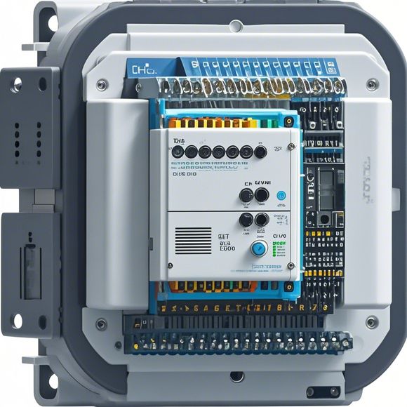
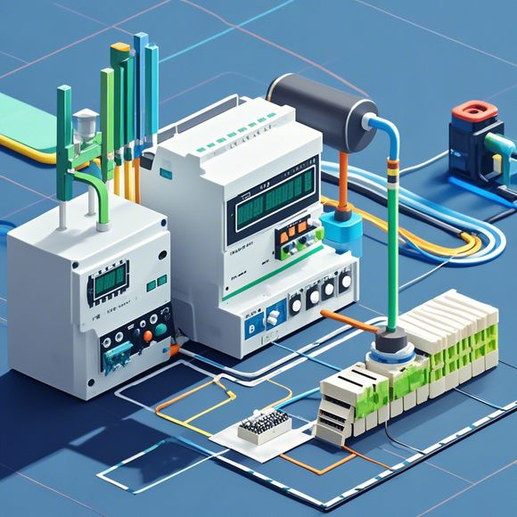
plc模块接线图
The plc module wiring diagram is an indispensable document that guides you through the process of connecting various devices to form a complete control system. It includes detailed information such as the input and output modules, sensors, switches, and other components.To begin with, let’s talk about the digital input modules, which are responsible for receiving signals from external devices like relays and sensors. The connection process involves inserting the U-shaped connector into the back of the module and then connecting it to the installation rail using a screwdriver. Next, plug the 4-way connector into the power supply unit (PM) on the installation rail. Once everything is connected securely, test the system for functionality.For the digital output modules, they control the operation of devices like relays and contactors by sending out signals. The procedure involves inserting the U-shaped connector into the back of the module and connecting it to the installation rail. Afterwards, insert the U-shaped connector into the digital input module's back and connect it to the installation rail. Finally, connect the output wires to the corresponding terminals on the device and check for proper functioning.When installing the CPU or PLC, ensure that all cable connections are secure and that there are no exposed wires that could lead to safety hazards. Also, pay attention to the voltage requirements specified on the power supply units and make sure that they match the specifications of your equipment.In conclusion, mastering the basics of plc module wiring diagrams can help you confidently troubleshoot issues and ensure that your automation systems work smoothly. With careful attention to detail, you can create a reliable and efficient control system that meets your needs.
"Mastering the Art of PLC Module Wiring: A Practical Guide for Successful Automation Projects"
Introducing this comprehensive guide to PLC module wiring, tailored specifically for those seeking to master the art of automation in their industrial projects. Whether you're a seasoned professional or a beginner just starting their journey, this resource provides an in-depth understanding of the key components and techniques involved in installing, configuring, and troubleshooting PLC modules. By following these step-by-step instructions, you can ensure that your automation projects are not only functional but also efficient and reliable. So let's dive into the details, shall we?

Firstly, it's important to note that PLC (Programmable Logic Controller) modules are essential components in modern industrial automation systems. Their ability to control complex processes with ease and precision makes them a valuable asset in manufacturing, healthcare, and other industries. However, their installation requires a certain level of technical expertise, and mistakes can lead to costly downtime or even safety hazards. That's where this guide comes in.
To start off, let's take a closer look at the various components that make up a typical PLC module wiring system. There are two main types of PLCs - analog and digital - each with their own set of wiring requirements. The analog PLCs use analog signals to convey data between the controller and the process, while the digital PLCs rely on digital signals. Additionally, there are three main types of PLCs - Ladder Logic, Function Block Programming, and PLD/Programmable Logic Devices (PLDs). Each type has its own set of wiring conventions and configuration options.
Now, let's get started with the first step - identifying the components and materials required for PLC module wiring. This will involve gathering the necessary tools, such as wire cutters, pliers, and multimeters, as well as a detailed knowledge of the electrical standards and regulations applicable to your specific industry. It's also important to consider the size and weight of the PLC module itself, as well as the overall design and layout of your automation system.
The next step is to plan out the wiring diagram based on the specifications provided in the manufacturer's manual or online documentation. This will help you determine the appropriate connections between the PLC module and other components in your system. Some common connection points include the input and output ports, power supply connectors, and communication interfaces (such as PROFIBUS, Ethernet, or USB). Additionally, you may need to consider factors such as signal polarity, voltage levels, and data rates when designing your wiring diagram.
Once you have completed the wiring diagram, it's time to begin the actual installation process. Begin by connecting the power supply cables to the PLC module and any other devices that require power. Then, connect the input and output ports to the appropriate sensors, valves, and actuators in your system. Be sure to label all connections clearly and follow the manufacturer's recommended procedures for handling and testing the wiring.
As you work through this guide, remember to keep in mind the importance of maintaining a clean and organized work area. This includes keeping all tools and materials neatly arranged and avoiding cross-contamination of different types of wires. Additionally, be sure to follow safety precautions throughout the process, including wearing protective gear and ensuring proper ventilation.
In addition to the practical steps outlined above, it's also crucial to understand the theoretical concepts behind PLC module wiring. This includes an overview of electrical circuits, signal processing techniques, and the principles of programmability. By gaining a deeper understanding of these concepts, you can confidently design and implement effective automation systems that meet your specific needs and goals.
Finally, don't forget to seek feedback from experienced professionals or colleagues who may have encountered similar challenges during their careers. Their insights and advice can provide valuable guidance and help you avoid common pitfalls along the way.
In conclusion, mastering PLC module wiring requires a combination of technical knowledge, hands-on experience, and a commitment to continuous learning. By following this guide and applying the practical tips and theoretical concepts outlined above, you can achieve success in your automation projects and build a solid foundation for future growth and development. Remember, investing in your education and skill acquisition is always worth it in the long run.

Content expansion reading:
Content:
Hey there! If you're new to the world of PLCs (Programmable Logic Controllers), or you're just looking to brush up on your knowledge, understanding PLC module wiring diagrams is a crucial step. These diagrams can seem intimidating at first, but once you know what to look for, they're actually pretty straightforward.
PLC modules are the building blocks of a PLC system. They perform various functions, from simple on/off control to complex data processing. When these modules need to communicate with each other or with other devices, they do so through a wiring diagram that specifies how they should be connected.
A typical PLC module wiring diagram will show you the following:
1、Inputs and Outputs: These are the points where the PLC module connects to other devices or systems. Inputs receive signals from sensors or switches, while outputs send signals to actuators or other control devices.
2、Power Supply: This is the source of power for the PLC module. It's important to ensure that the power supply is compatible with the module and that it's properly connected to the correct terminals.
3、Communication Ports: These are the interfaces that allow the PLC module to talk to other modules or systems. They can be serial, parallel, Ethernet, or any other type of communication protocol.
4、Functional Blocks: These represent the different parts of the PLC module, such as the CPU (Central Processing Unit), memory, and I/O (Input/Output) sections.

5、Wiring Instructions: The diagram will show how to connect the various parts of the PLC module together, as well as how to connect external devices.
When you're looking at a PLC module wiring diagram, here are some tips to help you make sense of it:
Read the Manual: Always start by reading the manual that comes with the PLC module. It will provide specific information about the module's functions and how to interpret the wiring diagram.
Understand the Symbols: Each component in the PLC module will be represented by a specific symbol. Make sure you understand what each symbol means.
Follow the Lines: The wiring diagram will show you how the different parts of the PLC module are connected. Follow the lines from one component to another to understand the flow of power and signals.
Check the Ratings: Make sure that the wiring is done according to the voltage and current ratings specified in the diagram. Using the wrong wiring can damage the PLC module or cause a safety hazard.
Test Your Work: Once you've wired everything up, it's important to test the system to ensure that it's working correctly. This might involve using a multimeter or other testing equipment.
Remember, safety is paramount when working with PLCs and electrical systems. Always follow proper safety procedures and consult with a professional if you're unsure about anything. With a bit of practice and knowledge, you'll be interpreting PLC module wiring diagrams like a pro in no time!
Articles related to the knowledge points of this article:
PLC Programming for Automation Control in the Manufacturing Industry
PLC (Programmable Logic Controller) Control System Basics
Plumbers Rule! The Role of PLC Controllers in the World of Waterworks
Connecting a PLC Controller to Your Computer
PLC Controllers: A Comprehensive Guide to Understanding Their Prices