PLC Controller Wiring Diagram: An Introduction to the Art of Connecting Electrical Devices
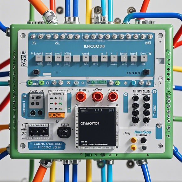
Sure, I'll try to create a concise summary for you based on the provided content."PLC Controller Wiring Diagram: The Art of Connecting Electrical Devices."This diagram represents a crucial aspect of electrical wiring, showcasing how various devices are connected in a logical and efficient manner. The PLC controller is the central hub, acting as a bridge between human operators and the machinery or automation system it controls. It interprets commands from these operators, translates them into instructions that control the movement of machines or other devices.To ensure smooth operation, this wiring diagram must be meticulously planned out. Each device and its corresponding connection point must be clearly marked, ensuring that each component can communicate effectively with the rest of the system. This diagram also provides vital details about potential hazards, such as overload protection circuits, which can help prevent accidents caused by faulty wiring.In essence, the PLC controller wiring diagram serves as a blueprint for ensuring safe and effective use of an automation system, demonstrating the importance of careful planning and understanding of electrical connections when working with complex machinery.
Dear fellow professionals,

I'm thrilled to share with you a crucial yet often overlooked aspect of our trade - the plc controller wiring diagram. It's more than just a mere diagram; it's a manual that tells you how your electrical systems work and communicate.
Imagine having an intricate puzzle with all the pieces laid out in front of you. Each piece has its specific function, and if you can't figure out where each one goes or what it does, you'll struggle to put the whole thing together. Similarly, when it comes to connecting plc controllers, understanding the wiring diagram is like knowing your way through this intricate puzzle.
The first step is to recognize that there are two main categories of wiring diagrams: functional and schematic. A functional diagram shows you exactly how each component works, while a schematic diagram provides a general layout of how the system should be connected. In this context, a schematic diagram will be the focus of our discussion, which will guide us through the process of connecting plc controllers.
Now let's dive into the details. A plc controller wiring diagram typically consists of several sections, including the power supply, input/output modules, communication modules, and so on. Each section has specific components that must be connected correctly for the system to operate as intended.
Let's start by talking about the power supply. This is where you connect the main power source to the plc controller. The voltage and amperage requirements must be met to ensure safe operation. It's important to note that not all controllers have the same power specifications; hence, it's essential to refer to the manual for accurate information.

Next, we have the input/output modules. These are responsible for receiving and sending signals to and from the controller. The wiring diagram will show you which pins correspond to inputs and outputs, and how they should be connected. For example, if the controller requires a high-speed digital input, you'll need to use a dedicated I/O card to provide it.
Moving on, let's discuss the communication modules. These are used for exchanging information between different components in the system. They might include network interfaces, RS-232/RS-485 ports, or even wireless connections like Wi-Fi or Bluetooth. The wiring diagram will detail how these modules are integrated into the overall system.
As you can tell, the plc controller wiring diagram is a comprehensive guide to ensuring your system operates safely and efficiently. It's not just a simple diagram; it's a blueprint that outlines the connections needed to bring your electrical components together.
Now, let's move on to some practical tips. Firstly, always read the manual thoroughly before starting any wiring project. It'll provide detailed information on the connection points and their functions. Secondly, practice makes perfect, so don't be afraid to experiment and try different connections. Thirdly, always test your connections before finalizing them; this will help identify any potential issues and prevent costly mistakes later on.
In conclusion, the plc controller wiring diagram is a vital tool for anyone working with electrical systems. By following the guidelines outlined in the diagram, you can ensure that your system runs smoothly and efficiently. Remember to read, practice, and test - these are the keys to a successful wiring project.

So, dear colleagues, let's embrace this responsibility and make sure our systems run seamlessly. After all, every connection counts in our quest for excellence in the world of automation.
Content expansion reading:
Articles related to the knowledge points of this article:
PLC Controller Selection Guide for Foreign Trade Operations
PLC Programming for Automation Control in the Manufacturing Industry
Plumbers Rule! The Role of PLC Controllers in the World of Waterworks
Connecting a PLC Controller to Your Computer
PLC Controllers: A Comprehensive Guide to Understanding Their Prices