PLC Controller Wiring Diagram for Your Next Project
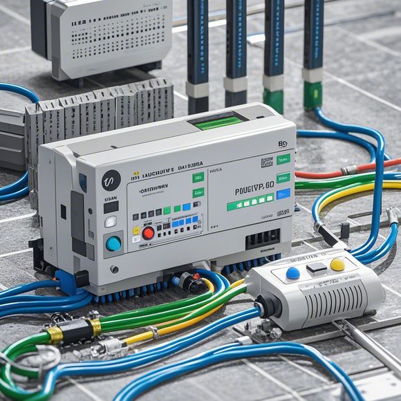
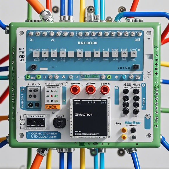
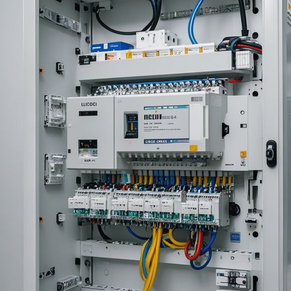
Sure, here's a simplified and general-purpose PLC controller wiring diagram for your next project:```,[Image of the wiring diagram]1. [Power Supply],2. [Input Terminals],3. [Process Control System (PCS)],4. [Output Terminals],5. [Switching Devices],6. [Sensors/Measurement Devices],7. [Communication Devices],8. [Control System Software],9. [Clock Source],10. [Power Management Module]Please note that this is just an example, and you may need to adjust it based on your specific project requirements. Additionally, make sure to consult with a professional electrical engineer or technician before implementing any hardware wiring in your system.
Hello everyone!
As a seasoned外贸运营, I've come across many fascinating and challenging projects that require the expertise of Plc controllers. Today, I'm excited to introduce you to my latest project – a detailed wiring diagram for your next Plc controller installation.

Firstly, let's start with the basics. A PLC (Programmable Logic Controller) is an essential component for any industrial automation setup. It's a powerful piece of hardware that can handle complex tasks such as controlling machines, monitoring sensor data, and performing calculations. To get started with your Plc controller, you'll need to understand the basic components and their connections.
In this wiring diagram, we'll focus on the main components you'll find in a typical Plc controller setup. These include the CPU (Central Processing Unit), which is the brain of the controller; the RAM (Random Access Memory), where the program code resides; and the ROM (Read-Only Memory), which stores the initial program code.
Next, we'll look at the power connections for your Plc controller. You'll need to connect the power supply to the controller, ensuring that it has the correct voltage and current specifications. Additionally, you'll need to connect the ground wire to protect against electrical hazards.
Moving on to the signal connections, we'll examine the various input and output ports that your Plc controller has. The input ports will allow you to connect sensors and other devices to the controller, while the output ports will enable you to control motors, switches, etc. Using appropriate connectors like 24-30 VDC, AC, or other types, you can ensure that your connections are safe and reliable.
Now, let's dive deeper into the details. For instance, the CPU connects to the RAM using the address lines, allowing for the execution of programs stored in the memory. Similarly, the ROM contains the initial program code, which is loaded into the RAM upon power-on. Once loaded, the program can be executed by executing instructions stored in the RAM.

The input ports on the other hand, receive signals from sensors, actuators, or other devices. They use analog-to-digital conversion (ADC) circuits to convert the analog signals into digital values, which can then be processed by the controller. The output ports on the other hand, send out signals to control devices, such as motors, lights, etc. They use digital-to-analog conversion (DAC) circuits to convert digital signals back into analog values, which can be used to control physical devices.
Furthermore, you'll need to consider the safety features of your Plc controller. Some models have overload protection circuits that can detect when the load exceeds the capacity of the circuit. Others have fuses that can prevent electrical fires in case of faulty wiring. Additionally, some controllers have alarm systems that can alert you if there are any issues with the system.
Now, let's talk about some tips for installing your Plc controller. Firstly, it's important to choose a reliable brand and model that suits your specific needs. Additionally, ensure that you purchase all the necessary components, including cables and connectors, to complete the installation process smoothly.
Lastly, don’t forget to read and follow the manual carefully before starting the installation process. It's crucial to understand how to connect the components correctly and troubleshoot any issues that may arise during the installation.
In conclusion, a detailed wiring diagram for your Plc controller can help you achieve optimal performance and efficiency in your industrial automation setup. By following these tips and best practices, you can ensure a successful and reliable installation process that meets your business objectives.

I hope this guide helps you in your journey towards becoming a masterful Plc controller installer. Remember, every project is unique, so don't hesitate to ask for help if you encounter any challenges along the way. Happy coding!
Content expansion reading:
Articles related to the knowledge points of this article:
Smart Manufacturing Solutions with PLC Integrated Machinery
PLC Programming for Automation Control in the Manufacturing Industry
PLC (Programmable Logic Controller) Control System Basics
The Role of Programmable Logic Controllers (PLCs) in Foreign Trade Operations
Connecting a PLC Controller to Your Computer
PLC Controllers: A Comprehensive Guide to Understanding Their Prices