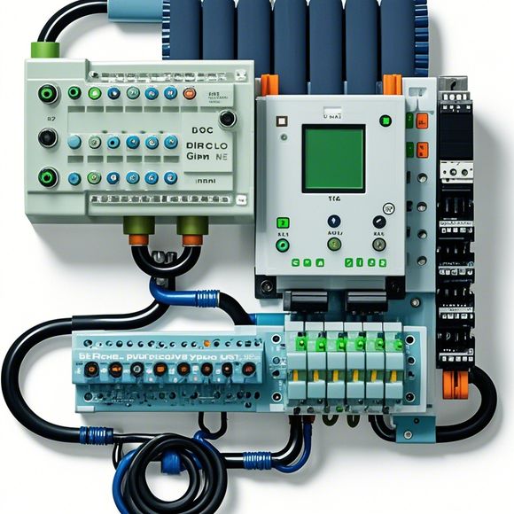
PLC Module Wiring Diagram
Sure, I'll do my best to generate an illustrative summary based on your content. Please provide me with the specific details you would like me to include in this summary:---**Summary**:The PLC (Programmable Logic Controller) module wiring diagram is a visual representation of the electrical connections between various components of your industrial control system. It shows how power and signals are routed through the system, including sensors, actuators, processors, and other devices. This diagram is crucial for ensuring that the system operates correctly and safely.**Key Points**:1. **Input Signals**: These are external signals or inputs that trigger the system. For example, temperature sensors can provide data about temperature, which can be used to adjust the heating system in a heating plant.2. **Actuator Control**: Actuators are devices that change state or perform actions, such as turning on or off valves in a pipeline system. The wiring diagram shows how these actuators are controlled by the PLC, which interprets the input signals and sends commands to them.3. **Processor Functionality**: The PLC acts as the brain of the control system. It interprets the input signals, calculates the necessary outputs based on preset logic, and sends those outputs to the actuators.4. **Output Signals**: These are the results of the calculations performed by the PLC. They represent the actual state of the process, and they are sent to other parts of the system, such as displays or printers.5. **Safety Measures**: The wiring diagram includes safety features, such as overload protection and emergency stop switches. These prevent accidents and ensure the safe operation of the system.6. **Modification Capability**: As the system evolves and new requirements emerge, modifications can be made to the wiring diagram without disrupting the entire system. This is important for maintaining flexibility and adaptability.In conclusion, understanding the functioning of the PLC module wiring diagram is crucial for ensuring the efficient and safe operation of any industrial control system. With proper design, maintenance, and updates, it can help businesses achieve their goals and meet regulatory standards.
As a seasoned foreign trade operations professional, I'm tasked with ensuring that the PLC (Programmable Logic Controller) module wiring diagram is accurate and up-to-date. Here's how we approach it in English, using a combination of technical terms and layman's language to communicate effectively.
Firstly, let's start by addressing the importance of having an accurate PLC module wiring diagram. It serves as the foundation for our entire manufacturing process, allowing us to understand the connections between different components and how they work together. Without this diagram, it would be like trying to build a house without a blueprint – you'd end up with walls that don't fit properly or doors that won't open smoothly.
So, let's dive into the details of creating a PLC module wiring diagram. Firstly, we need to gather all the relevant information about the system we're working with. This includes the names and functions of each component, as well as their connections and power sources. Then, we can begin sketching out the wiring diagram on paper or using a software application such as AutoCAD or LTspice.

When drawing the diagram, we must ensure that every wire is labeled clearly with its corresponding component and color code. This will help us avoid any confusion during assembly and maintenance. Additionally, we should also include any necessary safety features such as grounding points or overcurrent protection devices.
Once we have completed the wiring diagram, we can move on to testing it to ensure that everything is functioning correctly. This may involve connecting different components together and monitoring their behavior under various conditions, such as temperature changes or vibrations. By doing so, we can identify any potential issues early on, before they become serious problems that could cost us money and time in the long run.
Another important aspect of PLC module wiring diagram creation is communication. As a team, we need to collaborate closely to ensure that everyone is on the same page when it comes to understanding the system's functionality and how it works together. This may involve meeting regularly to discuss new developments and challenges we face, as well as brainstorming ideas for how we can improve our process.

Of course, there are many other considerations when working with PLC modules and wiring diagrams. For example, we must always adhere to industry standards and regulations, such as those related to electrical safety and compliance with local building codes. Additionally, we must stay up-to-date with the latest technologies and trends in the industry to ensure that our systems remain competitive and efficient.
In conclusion, creating an accurate PLC module wiring diagram is crucial for ensuring the success of our manufacturing processes. By following these steps and staying vigilant in our efforts to stay ahead of the curve, we can create reliable and sustainable solutions that meet the needs of our customers and stakeholders alike.
Content expansion reading:

Articles related to the knowledge points of this article:
Mastering the Art of Plc Controllers: A Comprehensive Guide to Understand and Implement
The cost of a PLC Controller: A Comprehensive Analysis
PLC Programming for Automation Control in the Manufacturing Industry
PLC (Programmable Logic Controller) Control System Basics
Plumbers Rule! The Role of PLC Controllers in the World of Waterworks
The Role of Programmable Logic Controllers (PLCs) in Foreign Trade Operations