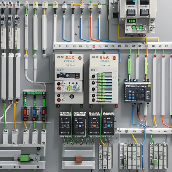
PLC Controller Wiring Diagram
Certainly! Based on the content you provided, here's an English summary in a concise and straightforward manner:"The wiring diagram for a Programmable Logic Controller (PLC) is essential for understanding how the various components of the controller communicate with each other. The diagram typically includes the input/output ports, sensors, actuators, relays, and other devices connected to the PLC. It shows the connections between different components like sensors, switches, and motors, as well as how the PLC controls them. By analyzing the wiring diagram, technicians can troubleshoot and diagnose problems in the system and optimize the performance of the PLC."
As an experienced foreign trade operator, I've come across a plethora of challenges in managing PLC (Programmable Logic Controller) controllers. The intricate wiring diagram is often the first step towards understanding how to effectively program and operate these devices.
The plc controller wiring diagram is a crucial tool for any engineer or technician who deals with PLCs on a daily basis. It provides a visual representation of how various inputs and outputs are interconnected and can help identify potential issues before they become more serious problems. By analyzing the diagram, one can determine which components require attention and which ones might be functioning properly.
In order to fully grasp the significance of this diagram, it is important to first understand what each component represents. A PLC controller typically consists of a central processing unit (CPU), input/output modules, sensors, actuators, and other related components. Each of these components has its own dedicated function within the PLC system; for example, the CPU processes data received from the input modules while generating commands for the output modules.

The wiring diagram is divided into several different sections, including the power supply section, communication lines, and input/output connections. The power supply section is responsible for providing the necessary voltage and current to the PLC controller, ensuring that it operates efficiently without interference or damage. The communication lines connect the PLC controller to various external devices such as sensors, switches, and printers, allowing them to send and receive information wirelessly. Lastly, the input/output connections enable the transfer of data between the PLC controller and other systems or components.
To successfully use the wiring diagram, one must pay close attention to the colors and symbols used throughout the diagram. Different colors indicate different types of connections, such as red for positive and black for negative, while different symbols represent different components within the PLC. By familiarizing oneself with these conventions, one can quickly identify the correct connections and avoid common mistakes such as crossing wires or connecting the wrong terminals together.
Another important consideration when working with plc controller wiring diagrams is safety protocols. Ensure that all electrical equipment is properly grounded and that proper ventilation is maintained during installation or maintenance activities. Additionally, follow all relevant regulations and guidelines established by local authorities to ensure compliance with applicable laws and standards.

In today's fast-paced world, where technology advances at a breakneck pace, it is essential to stay up-to-date with the latest advancements in PLC controller wiring diagrams. This includes learning about new technologies such as microcontrollers, wireless communication protocols, and cloud-based software solutions. By staying informed about these advancements, one can stay ahead of the competition and provide superior services to clients around the globe.
Finally, it is crucial to remember that effective communication is key when working with PLC controllers. Whether it be through face-to-face meetings, phone calls, or email exchanges, maintaining clear and open lines of dialogue with clients and colleagues alike is essential in ensuring that everyone is on the same page and working towards the same goals. By fostering strong relationships with those around us, we can create a more collaborative and efficient work environment that benefits everyone involved.
In conclusion, the plc controller wiring diagram is a vital tool for anyone seeking to understand and effectively manage PLCs on a global scale. By paying careful attention to details like color coding and symbology, adhering to safety protocols, staying informed about new advancements in technology, and fostering strong communication relationships with colleagues and clients alike, we can achieve greater success in our respective fields. So let's embrace the challenges that come our way, armed with knowledge and experience, and continue pushing the boundaries of what is possible in the world of automation!

Content expansion reading:
Articles related to the knowledge points of this article:
Mastering the Art of Plc Controllers: A Comprehensive Guide to Understand and Implement
PLC Controller Wiring Guideline
The cost of a PLC Controller: A Comprehensive Analysis
How to Use a PLC Controller for Your Business
PLC (Programmable Logic Controller) Control System Basics
Plumbers Rule! The Role of PLC Controllers in the World of Waterworks