Understanding the PLC (Programmable Logic Controller) Controller Wiring Diagram
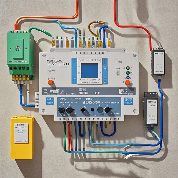
Sure, here's a summary of the information you provided in an English-language format:The PLC (Programmable Logic Controller) is a device used in industrial automation to control and monitor processes. The controller wiring diagram is essential in understanding how components on the PLC communicate with each other. It shows the connections between the input and output devices, as well as the internal components of the PLC. By examining the wiring diagram, one can identify the signals that are being sent from sensors or actuators, as well as the actions they will perform. This helps in designing and implementing effective control strategies for industrial processes.
In the world of international trade and manufacturing, understanding how to effectively use a Programmable Logic Controller (PLC) is crucial for optimizing production processes. A plc controller is an essential tool used in automation systems that can control various industrial processes. However, with so many components and wires involved in the wiring diagram, it can be challenging to navigate. That's why I'll share some tips on how to interpret and understand this important component of your PLC system.

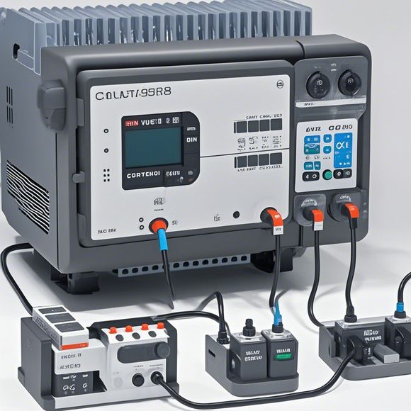
Firstly, let's talk about what a plc controller is. It's essentially a computerized device that can perform complex tasks like controlling machines and monitoring data. The wiring diagram is the visual representation of how these tasks are accomplished through the connection of various electrical components.
Now, let me give you a quick rundown of what we're dealing with here. The first thing we need to do is to identify the main components of the PLC. These include the CPU (Central Processing Unit), RAM (Random Access Memory), and various input/output modules. The CPU is responsible for executing programs stored on its memory, while the RAM stores temporary data.
Next, we should focus on the inputs and outputs of the PLC. An input is a signal that triggers the execution of a program, while an output is the result of that program. In our diagram, there will be lines connecting each input to its corresponding output. These lines represent the connections between the PLC and the other devices in the system.
Now, let's dive into the details. For instance, if we have an input called 'Switch1' connected to an output called 'LED' and another input called 'Switch2' connected to an output called 'Buzzer', then those lines in our diagram would indicate a direct connection between them. This means that when either switch is turned on or off, the LED or buzzer will light up or make a noise, respectively.

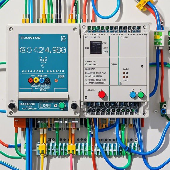
Another important aspect of the wiring diagram is the color-coding of wires. Each type of wire has a different color code, which helps us identify its purpose. For example, red wires represent live wires that carry current, while black wires typically serve as ground connections or neutral wires. Blue wires can be used for power supply, while yellow wires might be used for control signals.
Furthermore, the placement of the wires in the wiring diagram also matters. Some wires may be grouped together, indicating that they are connected in parallel, while others may be connected in series, indicating that they are connected in opposite directions. It's important to note that not all wires need to be connected to every component in the system. Some wires may only be necessary for one specific task or function.
Now, let's look at some common mistakes that beginners make when interpreting wiring diagrams. One common issue is overlooking certain components or connections. Another mistake is confusing wire colors or types, which can lead to confusion during assembly or troubleshooting.
To avoid these mistakes, it's helpful to practice reading and understanding the wiring diagrams of different systems beforehand. This way, you can familiarize yourself with the terminology used and become more comfortable with identifying different components and their connections.

Additionally, it's important to pay attention to any notes or comments provided by the manufacturer or technician who designed the system. These notes often offer valuable insights into how each component is wired and how it interacts with other parts.
In conclusion, understanding the PLC controller wiring diagram is crucial for anyone working in the field of automation. By following the tips and best practices outlined above, you can quickly become proficient at interpreting and maintaining this important component of your PLC system. Remember, with practice and patience, anyone can learn how to navigate this complex but rewarding world of industrial automation.
Content expansion reading:
Articles related to the knowledge points of this article:
How to Use a PLC Controller for Your Business
PLC (Programmable Logic Controller) Control System Basics
Connecting a PLC Controller to Your Computer
PLC Controllers: A Comprehensive Guide to Understanding Their Prices
Effective Strategies for Handling PLC Control System Faults
PLC Controller Advantages: A Comprehensive Guide for Success in Global Trade