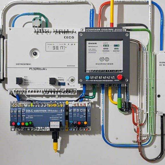
Mastering the Art of PLC Controller Wiring
As a seasoned trader in the world of international business, I've learned that mastery of technical details is often what separates the great from the average. In the realm of automation and control systems, where precise wiring can mean the difference between a smooth operation and a catastrophic failure, understanding the intricacies of programmable logic controller (PLC) wiring is paramount. Today, let's delve into the intricate dance of wiring PLC controllers, taking you through the steps, considerations, and tips that make this process both efficient and safe.
Firstly, it's essential to have a clear understanding of the basic components involved in PLC wiring. These include but are not limited to:

1、Power Supplies: The primary source of power for your PLC system. It's crucial to ensure that the power supply is stable and reliable, with adequate overload protection.
2、Input/Output Units (I/O): These units interface with other devices, such as sensors or actuators, and send or receive data based on the commands from the PLC.
3、Programmable Logic Controller: The heart of your PLC system, responsible for interpreting input data, making decisions, and outputting commands to the I/O units.
4、Connectors: These are the tiny plastic boxes that connect various electrical components together, ensuring a secure and reliable connection. It's essential to use appropriate types of connectors for each component to avoid damage or short circuits.
Now, let's dive deeper into the process of PLC controller wiring. Here's a step-by-step guide:
Step 1: Preparation
Before you start wiring, make sure your work area is clean and free of any obstructions. Remove any protective coverings on your PLC and I/O units to expose the connections.
Step 2: Layout Planning

Plan your wiring layout carefully, considering the placement of your PLC, I/O units, and connectors. Use diagrams to visualize your plan and make sure all components are accessible for future maintenance.
Step 3: Connecting the PLC
Connect the positive and negative terminals of your PLC to the appropriate power supplies. Ensure that all connections are firm and secure to prevent future issues.
Step 4: Connecting the I/O Units
Attach the appropriate I/O units to the PLC, ensuring they are securely connected. Test each connection to ensure proper functioning before moving onto the next step.
Step 5: Connecting the Connections
Using the correct connectors, connect the wires between different electrical components. Make sure to follow the manufacturer's instructions and avoid overloading connections.
Step 6: Protective Coverings

Once all connections are made, cover them with protective coverings to prevent accidental contact or damage. This step is crucial for safety and longevity of your PLC system.
Step 7: Testing
Test your PLC system thoroughly after completing all connections. Check if all inputs and outputs are working correctly and verify that the connections are secure without any loose ends.
In conclusion, understanding the intricacies of PLC controller wiring involves careful planning, precision, and attention to detail. By following these steps and guidelines, you can ensure a reliable and efficient operation of your PLC system. Remember, every connection counts, so take your time and do your job well. Happy wiring!
Content expansion reading:
Articles related to the knowledge points of this article:
PLC Controller for Manufacturing Automation
The cost of a PLC Controller: A Comprehensive Analysis
PLC Programming for Automation Control in the Manufacturing Industry