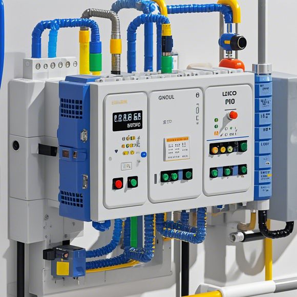
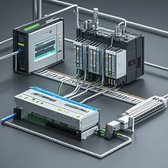
PLC Control Principle Diagram for Pump
Sure, here's a summary in English that corresponds to the content from your question:"The pump's PLC (Programmable Logic Controller) control system diagram illustrates how the controller manages the operation of the pump. The diagram shows the connections between the various components such as sensors, actuators, and control logic. It also indicates the flow of information from the sensors to the controller and the commands it sends to the pump to operate properly."
Hello, everyone! Today, I am going to talk about how to control a pump using a programmable logic controller (PLC) based on its principle diagram. A pump is an essential piece of equipment used in various industries, such as water treatment, chemical processing, and agriculture. To operate the pump efficiently and safely, we need to use a PLC system that can monitor and control various parameters like speed, pressure, and flow rate.
The first step in controlling a pump with a PLC is to understand its principle diagram. In this case, the PLC will be responsible for monitoring and adjusting the pump's speed, pressure, and flow rate. The pump will have sensors that detect various parameters such as water level, temperature, and flow rate, which will then feed back to the PLC. The PLC will then analyze the data and adjust the pump's speed, pressure, and flow rate to maintain optimal conditions for the process.

To achieve this, we need to connect various sensors and actuators to the PLC. For example, we can use a pressure sensor to measure the pressure inside the pipeline, a flow rate sensor to measure the flow rate of the water passing through the pump, and a temperature sensor to measure the temperature of the water. These sensors will send their readings to the PLC, which will then adjust the pump's speed, pressure, and flow rate accordingly.
Another important aspect of controlling a pump with a PLC is to ensure that the system is safe and reliable. This means that we need to implement various safety features such as over-speed protection, over-pressure protection, and fault shutdown. For example, if the PLC detects that the pump is operating at an excessively high speed or pressure, it will automatically reduce the pump's speed and pressure until it is within safe limits. Additionally, if there is any fault in the system, the PLC will shut down the pump immediately to avoid any potential risks.

In conclusion, controlling a pump with a PLC involves understanding its principle diagram and connecting various sensors and actuators to the PLC. By following these steps, we can create a reliable and efficient system that ensures optimal performance of the pump under different conditions.
Content expansion reading:

Articles related to the knowledge points of this article:
PLC Controller Selection Guide for Foreign Trade Operations
The cost of a PLC Controller: A Comprehensive Analysis
How to Use a PLC Controller for Your Business
PLC (Programmable Logic Controller) Control System Basics
Plumbers Rule! The Role of PLC Controllers in the World of Waterworks