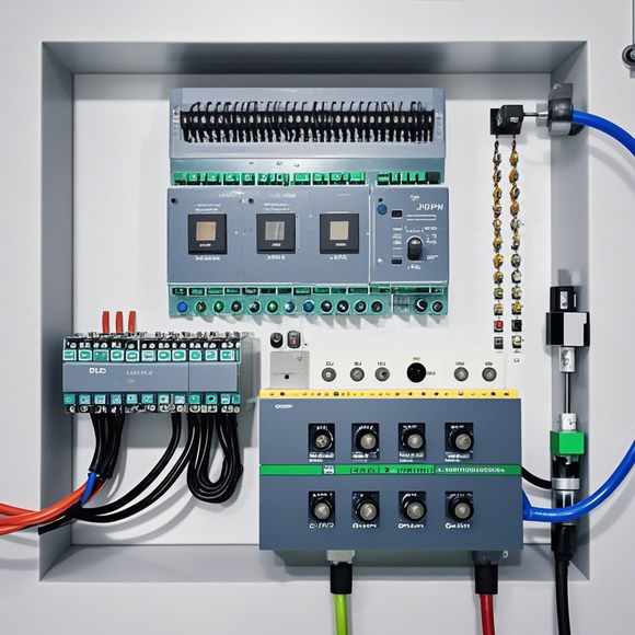
PLC Input/Output (I/O) Wiring Diagram for Foreign Trade Operations
Certainly, I'm here to assist you with creating a succinct summary of the PLC Input/Output (I/O) Wiring Diagram for Foreign Trade operations.---Title: PLC I/O Wiring Diagram for Foreign Trade OperationsAbstract:,This document provides a comprehensive overview of the PLC I/O wiring diagram required for foreign trade activities. It includes information on the different components and their connections, as well as guidelines for ensuring proper electrical design and safety. The diagram is designed to simplify the process of setting up and maintaining a reliable foreign trade system, which is essential for efficient and safe operations.Key Points:,- Overview of PLC I/O wiring diagram for foreign trade operations,- Components involved in the setup and configuration,- Guidelines for electrical design and safety considerations,- Importance of proper setup for effective trading activities,- Potential benefits of using this wiring diagram---This summary should provide readers with a clear understanding of the key points and importance of the PLC I/O wiring diagram for foreign trade operations.
In today's digital age, effective communication is critical for any business that aims to thrive in the global marketplace. For a company looking to expand its reach and increase efficiency through automation, understanding how to connect and control equipment like Programmable Logic Controllers (PLCs) is paramount. This guide will walk you through the process of creating a comprehensive I/O wiring diagram for your PLC system, ensuring every component works harmoniously to achieve your business objectives.
Firstly, it's essential to understand what an Input/Output (I/O) wiring diagram is. It serves as a visual representation of how various inputs are connected to various outputs within a PLC system. This diagram helps identify potential issues or errors that may arise during the programming and execution phases of PLC automation projects.
Now, let's dive into the key steps involved in creating such a diagram. The first step is to gather all the components needed to build the I/O wiring diagram. These could include switches, relays, sensors, actuators, etc. Once these components have been identified, it's time to determine how they are interconnected within the PLC system.

The second step involves mapping out the connections between the different inputs and outputs. This involves carefully selecting the appropriate terminal blocks for each component and ensuring that they are properly labeled with their corresponding functions and purpose. Additionally, it's important to note any specific requirements or constraints related to the wiring diagram, such as voltage levels or maximum current capacity.
Once the inputs and outputs have been mapped out, it's time to begin drawing the actual wiring diagram itself. This can be done using various software tools available for PLC programming and automation systems. The aim is to create a clear, easy-to-understand diagram that accurately represents the connections between the components and their respective functions.
One common mistake made by beginners when creating I/O wiring diagrams is not properly labeling the connections. This can lead to confusion and misinterpretation of the data being transmitted between the PLC and the various devices. It's important to use clear, concise language when labeling the diagram, including both numerical and alphabetical codes where necessary. Additionally, it's crucial to ensure that all labels are consistent throughout the entire diagram, regardless of the complexity or size of the project being worked on.
Another important aspect of creating an effective I/O wiring diagram is considering the safety aspects of the project. This includes ensuring that all connections are properly grounded and isolated from external sources of electrical noise or interference. It's also important to consider potential hazards associated with certain components, such as high-voltage switches or motors, and take steps to mitigate these risks through proper installation and maintenance practices.

Finally, it's essential to regularly review and update the I/O wiring diagram as new components or modifications are introduced to the PLC system. This ensures that the diagram remains accurate and up-to-date, providing a reliable reference point for all future development and implementation projects.
In conclusion, creating an effective I/O wiring diagram for a PLC system is no simple task, but by following the above steps and paying close attention to detail, any business looking to automate its operations can successfully implement this powerful technology. By carefully mapping out all connections between inputs and outputs, taking care to label each connection correctly and considering safety and maintenance aspects of the project, businesses can confidently move forward with their automation initiatives while ensuring maximum efficiency and reliability.
Content expansion reading:
Articles related to the knowledge points of this article:
Smart Manufacturing Solutions with PLC Integrated Machinery
PLC Controller Wiring Guideline
Plumbers Rule! The Role of PLC Controllers in the World of Waterworks
PLC Controllers: A Comprehensive Guide to Understanding Their Prices
What is a Programmable Logic Controller (PLC)
PLC Controller Advantages: A Comprehensive Guide for Success in Global Trade