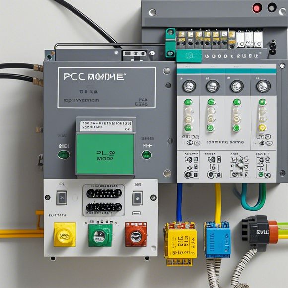
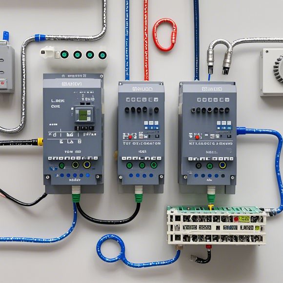
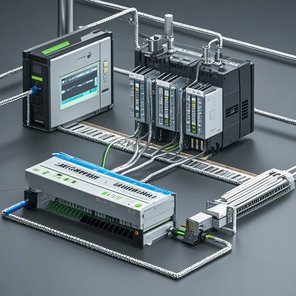
一张图看懂plc电路图
根据你提供的内容生成一段口语化英文摘要:Title: Understanding a PLC Circuit DiagramHello, everyone! Today, let's dive into the world of PLC circuit diagrams. These diagrams are like a map that shows you how to wire up your PLC system, making it easy for anyone to understand.Firstly, a PLC is a powerful piece of equipment used in industrial applications. It stands for Programmable Logic Controller. When we say "plc circuit diagram," we're talking about a visual representation of how different components are connected together. This diagram can be as simple or complex as you need it to be.One common feature of a plc circuit diagram is the use of symbols. These symbols are familiar to anyone who has worked with computers before, and they help make the diagram easier to read. For example, the symbol for an input device might look like this:[Insert image of the input device symbol]Similarly, output devices might look something like this:[Insert image of the output device symbol]But not all PLCs are created equal. Some have a simpler interface while others require more advanced programming. That's why it's important to choose the right type of PLC for your specific needs.When it comes to wiring, there are two main ways: direct wiring and using a controller. Direct wiring involves connecting each component to its respective terminal on the PLC. This method is straightforward but requires a good understanding of electrical circuits. On the other hand, using a controller takes care of many of the details for you. This saves time and effort, but it also means you need to learn a new set of commands.Now, back to those colorful images. Let's take a closer look at some examples of how these diagrams can be helpful. Say you're working on a machine that needs to start and stop. You could create a simple diagram like this:[Insert diagram of a starting and stopping process]In this diagram, you can see the different steps needed to get the machine started and stopped. Each step is represented by a different color, which makes it easy to identify where each part fits in.So, to summarize, a PLC circuit diagram is like a visual roadmap that helps you navigate through the world of electronics. Whether you're just starting out or need to update your knowledge, understanding these diagrams can make a big difference in your work.That's all for today! If you have any questions or want to chat more about this topic, feel free to leave a comment below or reach out to me anytime!
"Mastering Plc Circuit Diagrams with Pictures: Unlocking the Secrets of Electrical Integration and Automation"

Introduction:
Hello fellow techies, engineers, and automation enthusiasts! Today, we're embarking on a fascinating journey that will take us through the intricate world of Plc (Programmable Logic Controller) circuit diagrams. If you've ever been curious about how these marvelous devices work, or simply wish to enhance your understanding of electrical integration and automation, then this guide is perfect for you.
Plc circuit diagrams are a visual representation that helps engineers, technicians, and even non-professionals like yourself understand the intricacies of a particular piece of hardware or software. They serve as a comprehensive guide that not only explains the physical components involved but also deciphers the logical processes happening behind the scenes.
But before diving into the specifics of each component, let's first establish some ground rules for our exploration. Remember, while we'll be discussing the basics, there's no substitute for hands-on experience when it comes to understanding complex systems like Plc circuits. But fear not, as we'll provide you with a comprehensive overview that should help you grasp the concepts quickly.
Let's dive into the heart of Plc circuit diagrams and explore its various components step by step:
1、Input Signals:
- These are the primary triggers that initiate the flow of data in a Plc system. They can be analog signals such as sensor readings or pulse-width modulated (PWM) outputs from motor controllers, or digital inputs from other devices.
2、Output Signals:
- These are the final products that are sent out to control the actuators and interface with external devices. They can be simple voltage levels or high-speed digital signals.
3、Switches:
- The switches act as the gatekeepers between the input and output signals. Depending on their status, they either allow or block the flow of data.
4、Arbiters:
- Arbiters are responsible for determining which output signal gets sent based on the state of the switches. They ensure that the correct action is taken without conflict.

5、Memory:
- This is where the stored information resides, including program codes, settings, and configurations for the Plc system.
6、Process Control Loops:
- These loops define the sequence of operations that the Plc executes based on its memory. They include timers, counters, and sequencing logic.
7、External Device Interfacing:
- This section discusses how the Plc communicates with external systems like sensors, actuators, or other Plc systems. It includes communication protocols, data formats, and security measures.
8、Programming Languages:
- While the actual programming language may vary depending on the manufacturer, most Plc systems use a combination of ladder logic and function blocks for coding.
9、Safety Features:
- Safety features are essential to ensure that the Plc system operates safely and effectively under various conditions. They include protection against overheating, short-circuits, and other hazards.
10、Diagnostics and Testing Tools:
- To troubleshoot any issues, it’s crucial to have access to diagnostics tools that allow you to inspect the internal workings of the Plc system and test its functionality.
Now, let's delve deeper into each component to provide an in-depth understanding:

1. Input Signals: Understanding what goes into a Plc is critical because these signals dictate how the system responds to changes in the world around it. You'll learn about different types of inputs like analog or digital signals, and how they interact with each other. The importance of ensuring clean and reliable signals cannot be understated—it's the foundation upon which all else hinges.
2. Output Signals: Once the Plc receives its commands, it transforms them into actionable output signals using its processing capabilities. Understanding how these signals are produced and controlled is vital to ensuring that your system performs as expected. From simple power levels to complex digital protocols, the possibilities are endless.
3. Switches: These gateways play a crucial role in controlling the flow of data within the Plc system. By analyzing the behavior of these switches, you gain insights into how they influence the overall performance of your system. Whether they operate as enable or disable signals, understanding their functions is crucial for maintaining optimal operation.
4. Arbiters: These are the key decision-makers within your Plc system, determining which output signal gets executed next based on the current state of the switches. Mastering the art of arbitration ensures that your system remains responsive and efficient under varying conditions.
5. Memory: The storage element within your Plc plays a critical role in preserving the state of your system at any given moment in time. By examining its structure and capabilities, you can better understand how it enables smooth and seamless transitions between states, ensuring that your system operates reliably and predictably.
6. Process Control Loops: These are the core engine of your Plc, driving the system towards its desired outcome through a series of interdependent steps. By studying their architecture and operation, you gain a deep understanding of how they coordinate and manage the system's resources efficiently and effectively.
7. External Device Interfacing: This is where your Plc meets the world outside of its confines. By exploring how it communicates with various external systems, you develop a better appreciation for how interconnectivity can shape your entire workflow or process.
8. Programming Languages: While the specific syntax and structures may vary, programming languages are the backbone of every Plc project. By mastering these tools, you gain the ability to express complex logic and create custom solutions tailored to specific needs.
9. Safety Features: As safety regulations become increasingly stringent in the industrial world, understanding how your Plc implements safeguards is essential. By examining its design and implementation, you can identify potential risks and take proactive measures to mitigate them.
10. Diagnostics and Testing Tools: In today's fast-paced world, it's more important than ever to have access to effective diagnostic tools. By leveraging these tools, you can uncover hidden issues, optimize your system's performance, and ensure long-term reliability.
In conclusion, exploring Plc circuit diagrams requires a blend of analytical thinking and hands-on experience. By mastering the basics of each component discussed above, you'll gain a profound understanding of how these systems work together to create highly efficient and reliable workflows. So, grab your pen and pencil, open up your favorite diagramming software, and get ready to embark on an exciting journey of discovery and growth.
Content expansion reading:
Articles related to the knowledge points of this article:
Smart Manufacturing Solutions with PLC Integrated Machinery
PLC Controller Selection Guide for Foreign Trade Operations
Mastering the Art of Plc Controllers: A Comprehensive Guide to Understand and Implement
The cost of a PLC Controller: A Comprehensive Analysis
PLC Programming for Automation Control in the Manufacturing Industry