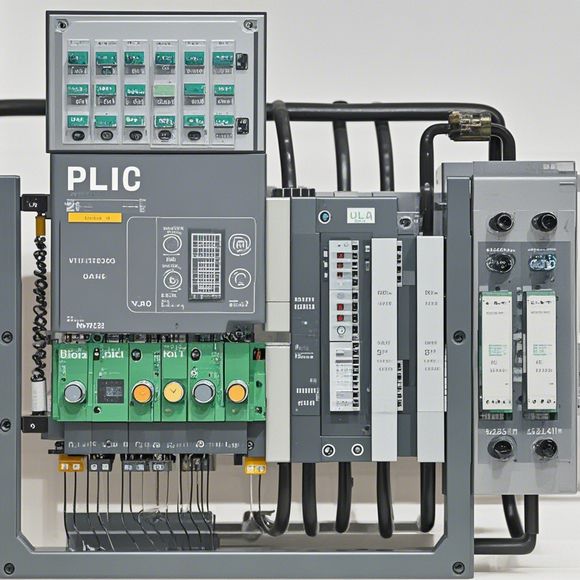
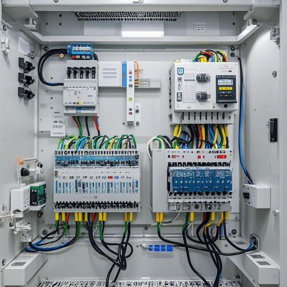
PLC Controller Wiring Diagram
Sure, here's a concise summary of what you provided in English:"The PLC controller wiring diagram shows the electrical connections between various components within the PLC system. It includes details such as power supply connections, input/output modules, sensors, actuators, and communication interfaces. This diagram is crucial for understanding how different devices interact with each other to achieve automation tasks."
As a foreign trade operations manager, understanding the intricacies of our product's PLC controller wiring diagram is crucial. It serves as the foundation upon which we build our business operations and ensures that all systems function seamlessly and effectively. In this regard, I am going to provide you with a detailed explanation of how to properly connect the PLC controller wires.
First and foremost, it is important to understand the basic components of the wiring diagram. This includes the main control unit (PLC), sensors, actuators, input/output modules, and other peripheral devices. Each component has its own set of wires, connections, and configurations, which must be accurately mapped out on the wiring diagram. This helps us to identify the correct connections for each device and ensure that everything is securely grounded.

Now, let’s discuss the process of connecting the PLC controller wires. The first step involves identifying the various types of connections required for each component. For example, sensors typically have inputs connected to their respective circuit boards, while outputs are connected to the control unit. Similarly, actuators require power lines and communication lines, while input/output modules have both input and output ports.
Once we have identified the connections, we need to carefully measure the appropriate length of wire needed to connect each component. This is essential to prevent any short circuits or overheating due to improperly sized wires. We also need to ensure that all wires are securely insulated and labeled with proper voltage ratings and connections.
Next, we need to install the wires into the appropriate terminal blocks or sockets on the PLC controller. This requires careful attention to detail, as any errors can lead to unintended connections or circuit failures. We should also check for any corrosion or damage in the wires before installing them, as this may affect their electrical resistance or performance.
Once all the wires are installed correctly, we need to secure them using cable ties or other appropriate fasteners, depending on the manufacturer's recommendations. We should also make sure that all connections are properly labeled, so that future maintenance or repairs can be easily performed without causing any disruptions in production.

In addition to these steps, it is important to follow any specific guidelines or recommendations provided by the manufacturer for connecting the PLC controller wires. These guidelines may include details such as voltage levels, signal transmission frequencies, or even specific color codes used for marking different types of connections. Following these guidelines will help us to ensure that the system operates correctly and efficiently throughout its lifespan.
Another critical aspect of connecting PLC controller wires is ensuring proper testing after installation. This involves checking for any short circuits, overheating, or other issues that may arise from incorrect connections. We can use specialized tools such as multimeters and oscilloscopes to test the system and detect any faults or errors that may have been missed during the installation process.
Furthermore, we should also consider implementing a regular monitoring and maintenance program for our PLC controller system. This will allow us to identify any potential issues early on in the system's lifespan, allowing us to take proactive measures to address them before they become more serious problems. By regularly inspecting the wires and other components, we can catch potential issues before they cause any significant disruptions or downtime.
In conclusion, connecting the PLC controller wires is an important step in ensuring the proper functionality and efficiency of our system. By following proper installation procedures, testing methods, and regular maintenance programs, we can minimize risks associated with incorrect connections and ensure a reliable and robust PLC controller system. Remember to stay up-to-date with the latest best practices and consult with experts when necessary to ensure that your system is always running at its peak performance level.

Content expansion reading:
Articles related to the knowledge points of this article:
PLC Programming for Automation Control in the Manufacturing Industry
PLC (Programmable Logic Controller) Control System Basics
The Role of Programmable Logic Controllers (PLCs) in Foreign Trade Operations
PLC Controllers: A Comprehensive Guide to Understanding Their Prices