Introduction to PID Controller Wiring Diagrams
Sure, I can provide you with an outline for a 200-300 word summary on PID controller wiring diagrams. Here's a rough draft:---**PID Controller Wiring Diagrams Overview**A PID (Proportional-Integral-Derivative) controller is a type of feedback loop that adjusts the output of a system based on its error between the desired and actual outputs. This controller has three main elements: Proportional (Kp), Integral (Ki), and Derivative (Kd). Each element contributes to the overall behavior of the controller.In order to understand how these components work together, one needs to understand the basic structure of a PID controller. A typical PID controller consists of a proportional, integral, and derivative part. The proportional part responds to changes in the error signal directly, while the integral part takes into account past errors. The derivative part predicts the rate of change of the error.The wiring diagram for a PID controller is designed to show the connections between various parts of the controller circuit. It typically includes wires that connect the inputs (e.g., sensor signals or control commands), the proportional, integral, and derivative components, and the outputs (e.g., actuator signals). The wiring diagram also shows the voltage levels required for each component.Understanding a PID controller wiring diagram is crucial for troubleshooting and debugging systems that use PID control. By examining the connections between different components, one can identify issues with the controller such as incorrect settings or broken wiring.In conclusion, PID controller wiring diagrams are essential for understanding how a PID controller works and how it can be used to control systems. By following the basic structure of a PID controller and examining its wiring diagram, one can effectively diagnose and troubleshoot PID-based systems.
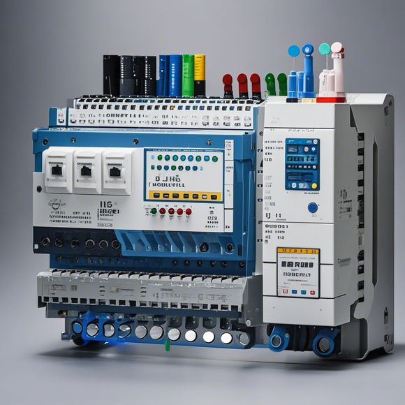
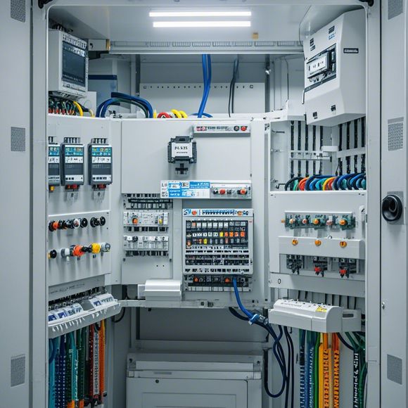
As a professional in the field of foreign trade operations, you may be required to understand the basics of PLC controller wiring diagrams. These diagrams serve as a crucial tool for understanding how different components within an industrial automation system are connected together. In this guide, we will delve into the details of what each component represents and how it interacts with one another to create a functional system.
The first step in understanding the PLC controller wiring diagram is to familiarize yourself with the various components present in the system. These include sensors, actuators, processors, communication interfaces, and power supplies. Each of these elements plays a unique role in ensuring that the system operates efficiently and effectively.
One of the key components in a PLC controller is the processor, which is responsible for processing data from sensors or other inputs and generating commands for actuators based on the input data. The processor receives data from sensors and analyzes it in real-time to make decisions about the appropriate actions to take. This allows for quick response times and efficient control of the system.
Another crucial component is the communication interface, which allows for the transmission of data between different components of the system. This could include communication protocols like Ethernet, Profibus, or Modbus, depending on the specific application requirements. The communication interface enables seamless integration between different systems and devices, improving overall efficiency and performance.

Sensors and actuators are also essential components in a PLC controller system. Sensors detect changes in the environment or physical conditions, such as temperature or pressure, and send this information to the processor for analysis. Actuators respond to the instructions from the processor and adjust themselves accordingly, such as opening or closing valves or motors.
The power supply plays a critical role in maintaining the stability and functionality of the system. It ensures that all components are powered correctly and that there are no overloads or short circuits that could damage the system. Additionally, it provides backup power in case of emergency situations, such as power failures or unexpected shutdowns.
To fully comprehend the workings of a PLC controller wiring diagram, it is important to have a solid understanding of the different types of connections that exist between components. Common connections include wires, cables, and connectors. For example, wires connect sensors and actuators to the processor, while cables provide a physical pathway for the electrical signals to travel between components.
Connectors are used to secure and protect the wires and allow them to be easily plugged into the appropriate ports. They come in different sizes and configurations, depending on the specific needs of the system. Connectors can be used to connect multiple sensors or actuators to the processor at once, making it easier to manage complex systems without needing to physically modify the wiring diagram.
In addition to understanding the different connections, it is also important to recognize the importance of proper installation and maintenance. Proper installation ensures that components are properly positioned and secured, preventing any damage or misalignment that could disrupt the system's operation. Regular maintenance helps to identify and repair any issues before they become major problems, reducing downtime and increasing efficiency.

When it comes to troubleshooting a PLC controller wiring diagram, it is crucial to identify the source of the issue and address it quickly. This may involve checking for loose connections, identifying damaged or worn-out components, or diagnosing issues with the communication interface. It may also be necessary to consult a professional for assistance if the issue cannot be resolved on your own.
In summary, understanding the basics of PLC controller wiring diagrams is essential for anyone involved in industrial automation. By familiarizing yourself with the components and their interactions, you can better navigate complex systems and ensure that they operate efficiently and effectively. Remember to prioritize proper installation and maintenance, and always seek out help when needed. With this knowledge, you can confidently handle any challenges that may arise in your industry operations.
Content expansion reading:
Articles related to the knowledge points of this article:
PLC Controller for Manufacturing Automation
The cost of a PLC Controller: A Comprehensive Analysis
How to Use a PLC Controller for Your Business
PLC (Programmable Logic Controller) Control System Basics
Connecting a PLC Controller to Your Computer
PLC Controllers: A Comprehensive Guide to Understanding Their Prices