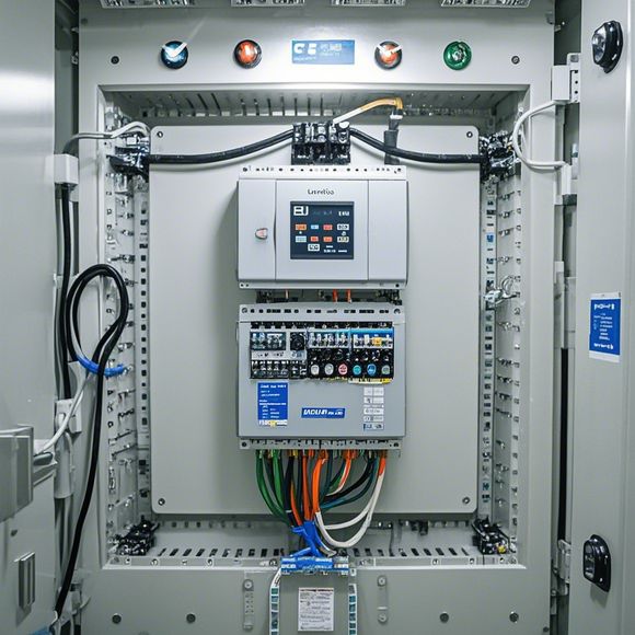
plc控制器接线图
Sure, here's a summary in English based on the content you provided:"PLC controller wiring diagram"This refers to an electrical diagram illustrating how different components of the Programmable Logic Controller (PLC) are connected together to control and monitor industrial processes. The diagram includes details like wire colors, connectors, and pin configurations, which help engineers understand how the PLC is interconnected with other devices in the system. It also shows the input and output modules, their connections, and the functions they perform within the overall PLC setup. This helps in ensuring that the correct signals are being sent from the sensors to the actuators, thereby maintaining accurate and reliable control over the industrial equipment.
"PLC Controller Wiring Diagram: A Guide To Understanding and Troubleshooting Electrical Interconnections for Factory Automation Systems."
Content:
Hey there! As a seasoned外贸运营, I've got some exciting news for you. Today, we're diving into the world of PLC (Programmable Logic Controller) controller wiring diagrams, which are essential tools for ensuring that your factory automation systems run smoothly. So let's take a deep dive into this fascinating topic together!

First off, let's start by understanding what a PLC controller is. It stands for Programmable Logic Controller, a type of electronic device that's designed to control various industrial processes. These controllers can be programmed to perform complex tasks like monitoring, controlling, and analyzing data from sensors or other devices in real-time. They're often used in manufacturing plants, refineries, chemical plants, power generation stations, and more, as they can automate many aspects of these industries.
Now, onto the subject of wiring diagrams. A wiring diagram is a visual representation of all the electrical connections between various components in a system. When working with PLC controllers, it's crucial to have a clear understanding of the wiring diagram to ensure that everything is wired correctly. Here's what you need to know about wiring diagrams for PLC controllers:
1、Component Location: The first step is to locate the various components in the factory, such as sensors, motors, actuators, switches, relays, and others. This will help you understand how they are interconnected and what their functions are.
2、Wire Colors: Each manufacturer has its own color coding for wires, which is important for accurate connection. For example, red wires are typically used for ground, yellow for live, black for common, and white for power. You should refer to the manufacturer's manual or schematic to ensure you're using the correct colors for each wire.
3、Connection Points: Look for connection points on the wiring diagram. These are where you'll connect wires to each component. For example, you might see "L" connections for long wire runs or "C" connections for short wire runs. Make sure to follow the manufacturer's instructions when connecting wires to these connection points.
4、Power Source: Determine the power source for your PLC controller. Most modern PLCs use AC power, but some may require DC power. Make sure to check the wiring diagram for the correct voltage and current requirements for your specific controller.

5、Safety Features: Many PLC controllers come with safety features like overload protection, fault detection, and emergency stop buttons. Look for these features and make sure they're connected properly.
6、Programming: Once you have a good understanding of the wiring diagram, you can begin programming your PLC controller. This involves setting up codes for each component and making sure that everything works as expected.
7、Testing: Once everything is wired up, it's time to test your PLC controller. Use a multimeter or other testing equipment to verify that all connections are correct and that the PLC is running properly. If there are any issues, make sure to troubleshoot them and fix them before continuing with the next steps.
In conclusion, working with PLC controller wiring diagrams can seem like a daunting task at first, but with patience, practice, and a little bit of knowledge, you'll be able to navigate this process with ease. Remember to consult the manufacturer's manual for any specific details regarding your particular model or application. Good luck out there!
Content expansion reading:
Articles related to the knowledge points of this article:
Smart Manufacturing Solutions with PLC Integrated Machinery
PLC Programming for Automation Control in the Manufacturing Industry
How to Use a PLC Controller for Your Business
Plumbers Rule! The Role of PLC Controllers in the World of Waterworks
The Role of Programmable Logic Controllers (PLCs) in Foreign Trade Operations