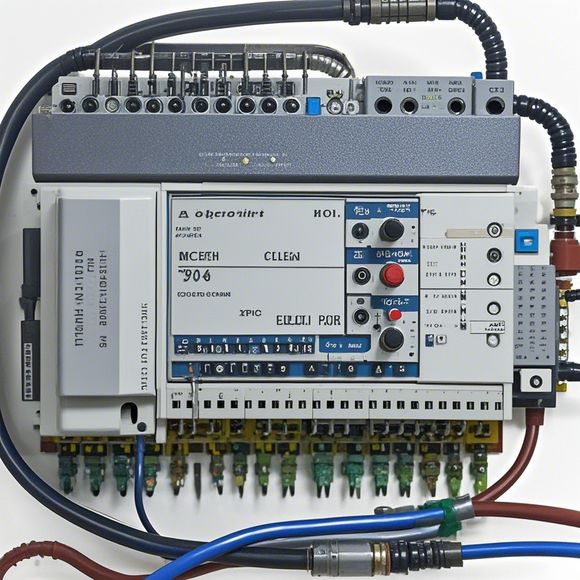
PLC Controller Wiring Diagram - An Interactive Guide for Beginners
In this beginner-friendly guide, we'll explore the PLC Controller Wiring Diagram. This diagram is a visual representation of how the various components of a PLC system are connected and interconnected. By understanding the wiring diagram, you will be able to troubleshoot any issues that arise in your PLC setup.The wiring diagram typically includes labels for all the components such as sensors, motors, actuators, switches, etc. Each label corresponds to a specific component, and each wire is connected to its respective component. The wire colors can also indicate the type of connection, for example, red wires for live wires, and black wires for ground wires.To navigate through a PLC wiring diagram, it's important to start at the top left corner and work your way towards the bottom right. You should pay attention to any special symbols or codes that may represent specific functions or connections. It's also essential to understand the relationship between different components in the PLC setup. For instance, if you have a motor, it will be directly connected to a control unit, which then controls the output of the motor via a relay.In summary, a PLC Controller Wiring Diagram provides an easy-to-understand visual representation of a PLC system's components and their connections. With this guide, you'll be able to quickly identify any potential issues and troubleshoot them efficiently.
Dear readers,
Welcome to our tutorial on the PLC controller wiring diagram. As a seasoned trader in the field of automation and control systems, I understand how important it is to have an accurate understanding of your PLC controller's wiring schematics. That's why we'll be covering every step you need to follow to properly wire up your PLC system.
Let's start by examining the basic components that make up a typical PLC controller wiring diagram. There are three main parts: inputs, outputs, and interconnections. The input section includes sensors and actuators that feed data into the PLC. The output section contains relays or motor controllers that send commands to the outside world. And the interconnections section consists of power supplies, switches, and other electrical connections that allow these components to work together harmoniously.
Now, let's delve into the detailed steps of creating a PLC controller wiring diagram. The first thing you need to do is to identify all of your sensors and actuators. You should label each component clearly so that you can easily refer back to them later. Once you have identified your components, you need to determine their respective connections to the PLC. This usually involves connecting the sensors or actuators directly to specific ports on the PLC's CPU module.

Next, you'll want to connect the power sources to the appropriate terminal blocks on the PLC. These terminal blocks are like batteries in a car; they provide the necessary voltage and current to power your components. Be sure to use the correct polarity and voltage rating when connecting your devices.
Once you've completed the wiring, test your system to ensure everything is working correctly. This may involve running tests on your sensors and actuators to verify that they are receiving and sending signals as expected. If any issues arise, don't hesitate to consult your manual or seek help from a professional engineer.
In conclusion, mastering the art of PLC controller wiring is essential for anyone who wants to operate a sophisticated industrial system. By taking the time to learn about the basic components and detailed steps involved in creating a wiring diagram, you can ensure that your PLC system is reliable and efficient. So grab a marker and pen, and let's get started!

Content expansion reading:
Articles related to the knowledge points of this article:
PLC Programming for Automation Control in the Manufacturing Industry
PLC (Programmable Logic Controller) Control System Basics
The Role of Programmable Logic Controllers (PLCs) in Foreign Trade Operations
Connecting a PLC Controller to Your Computer
PLC Controllers: A Comprehensive Guide to Understanding Their Prices