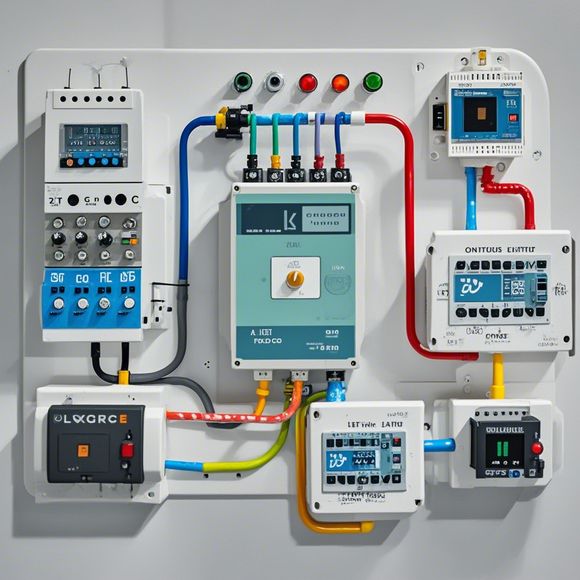
Industrial PLC Input-Output Mapping Guide
Industrial PLC (Programmable Logic Controller) is a crucial component in manufacturing automation. The Input-Output (I/O) mapping guide provides the detailed steps and considerations for creating a mapping between inputs and outputs of a PLC. It includes identifying the sensors, actuators, and devices that need to be connected, determining the appropriate pinouts and connections, ensuring compatibility with other systems or equipment, and testing to ensure proper functioning. This guide is essential for ensuring that all I/O connections are properly managed and that the PLC can perform its functions efficiently.
Hello, everyone! Today, I'm excited to share with you a comprehensive guide on the Input-Output mapping of Industrial PLC. It is crucial for understanding how these devices interact and control various industrial processes.
Firstly, let's understand what an Industrial PLC is. An Input-Output (I/O) Mapper is a tool that converts data from one system into another format, enabling easier communication between different components. This is especially important in industrial settings where precision and accuracy are critical.
Now, let's dive into the details. The first step in mapping is to identify the input signals that will be used by the PLC. This could range from temperature sensors measuring the temperature inside a furnace, to pressure sensors monitoring the pressure levels in a pipeline. Each input signal must be carefully analyzed to determine if it can be directly connected or requires a conversion process.
Once we have identified the inputs, the second step is to map them to the corresponding outputs. For example, if we have a temperature sensor that reads the temperature inside a furnace, the output could be a PWM (Pulse-Width Modulation) signal that controls a motorized heating element. The output signal should accurately represent the current state of the furnace temperature.

The next step is to connect these inputs and outputs to the PLC's I/O ports. Each port has a specific function; some are used for digital inputs, while others handle analog outputs. Therefore, it is essential to choose the right type of port based on the type of signal being sent or received.
Once all connections are made, we need to test the system to ensure everything works as expected. This involves running simulations, checking for any errors, and adjusting the connections if necessary. Once everything is working correctly, we can move onto more advanced topics such as programming languages like C, Assembly, Python etc. These allow for greater flexibility in controlling and managing the PLC's operations.
In conclusion, mapping an Industrial PLC's Input-Output is a crucial step in ensuring smooth operation of the system. By following this guide, you can effectively connect different systems together and achieve precise control over industrial processes. Don't hesitate to reach out if you have any questions or need further assistance.

Content expansion reading:
Articles related to the knowledge points of this article:
PLC Controller Selection Guide for Foreign Trade Operations
PLC Controller for Manufacturing Automation
PLC Programming for Automation Control in the Manufacturing Industry
How to Use a PLC Controller for Your Business
Plumbers Rule! The Role of PLC Controllers in the World of Waterworks