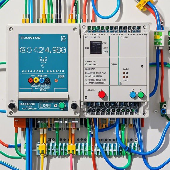
PLC Module Connection Diagram
Sure! Based on your content, here's a simplified version of an English summary:,"The PLC (Programmable Logic Controller) is a device that controls the flow of electricity in industrial processes. The PLC module connection diagram illustrates how different components of the PLC are connected to each other and communicate with each other."
Dear all,
I am excited to share with you the latest update on our company's product development and market expansion strategy. As a dedicated team member, I have been working diligently to enhance our product quality and customer service, while also focusing on expanding our global reach. Today, I would like to introduce you to our latest innovation in the field of industrial automation - the PLC module connection diagram.
This document is designed to provide a detailed guideline for installing and configuring PLC modules in various industrial settings. It covers everything from basic installation steps to advanced programming techniques, ensuring that our customers can easily connect their PLC modules to their systems and achieve optimal control performance.
Firstly, let's talk about the importance of having a clear understanding of the PLC module connections diagram. This diagram serves as a reference point for technicians who are responsible for installing and programming PLC modules in their respective systems. It provides a visual representation of the electrical connections between the PLC modules and their respective sensors, actuators, and other components. By following the diagram closely, technicians can ensure that the correct wires are connected at the right locations, avoiding potential issues such as short circuits or overheating.

In addition to providing a comprehensive guide to the installation process, this diagram also includes detailed instructions on how to program the PLC modules using various programming languages such as Ladder Logic, Function Block Diagrams, and PLD Programs. By learning these skills, technicians can quickly diagnose and resolve any issues that arise during the installation process, ensuring that their systems remain reliable and efficient.
Furthermore, this diagram highlights some common mistakes that technicians may make during the installation process. For example, not connecting all necessary wires or improperly positioning the PLC modules may result in system failures or reduced performance. By avoiding these mistakes, we can help our customers avoid costly repairs and minimize downtime.
Finally, this diagram also includes information on how to troubleshoot issues that may arise during the installation process. Whether it's a problem with a specific PLC module or an unresponsive control panel, knowing how to identify and resolve these issues can save time and money. Additionally, it offers guidance on how to optimize the performance of your PLC systems by implementing best practices such as regular maintenance and software updates.

In conclusion, the PLC module connection diagram is more than just a technical document - it is a valuable resource for our customers who need to install and maintain their industrial automation systems. By following these guidelines and tips, you can ensure that your systems run smoothly and efficiently, maximizing productivity and reducing costs. So why wait? Let us show you how to get started today!
Content expansion reading:
Articles related to the knowledge points of this article:
PLC Programming for Automation Control in the Manufacturing Industry
Connecting a PLC Controller to Your Computer
Understanding the Core Components of a Programmable Logic Controller (PLC)
PLC Prices: Navigating the Market with Clarity
PLC Control Cabinets: Understanding Prices & Factors Affecting the Cost
Overview of the Four Modules of Programmable Logic Controllers