PLC (Programmable Logic Controller) Controller Wiring Diagram Explanation
Sure, here's a summary in English that captures the essence of your content:The Programmable Logic Controller (PLC) wiring diagram explains how electrical connections are organized to communicate with the PLC hardware. This includes identifying the various components such as input and output modules, power supplies, and communication protocols used to control various processes. The diagram helps technicians understand how to configure the PLC for specific applications and troubleshoot any issues that arise during the installation or operation of the system.
As a foreign trade operation, understanding the wiring diagram for a Programmable Logic Controller (PLC) is crucial for ensuring smooth operations and troubleshooting any issues that may arise. Here's an explanation of the plc controller wiring diagram in English:
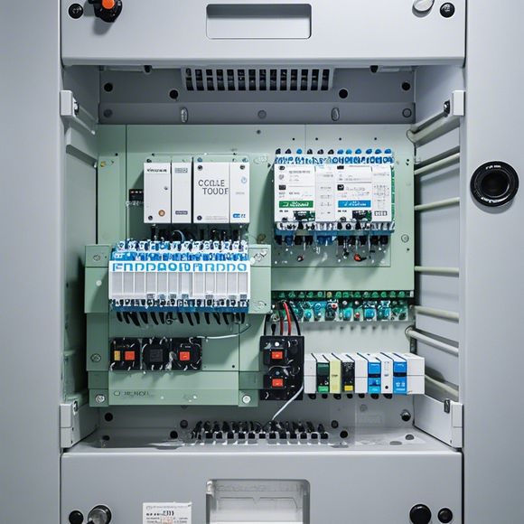
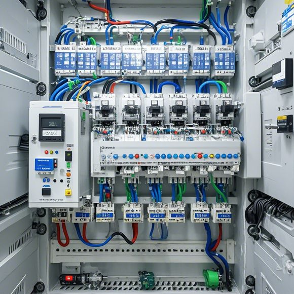
Firstly, let's take a look at the basic structure of a typical PLC controller wiring diagram. This typically includes components such as the input/output (I/O) modules, communication modules, and various sensors and actuators. The wiring diagram typically follows a systematic layout, showing how different signals are routed to and from different components within the PLC system.
For instance, let's say we have a simple PLC wiring diagram with three I/O modules, one communication module, and two sensors. The I/O modules would be connected to various devices within the control system through wires, while the communication module would connect to external devices like computers or other PLCs for sending or receiving data. The sensors would measure various parameters such as temperature, pressure, or flow rate and send their readings to the PLC via analog or digital inputs.
Now, let's talk about how the wiring diagram works. Each component in the PLC system has its own dedicated wires, which are connected to corresponding terminals on the board. The connections between components can be either direct or through switches and relays, depending on the complexity of the control system. For example, if we have a motor driver, it would likely require two wires for power and ground connections, while a temperature sensor might use four wires for temperature measurement.

Furthermore, there are also safety considerations when wiring the PLC controller. It's important to ensure that all connections are properly shielded to prevent electromagnetic interference and to comply with local electrical codes and regulations. Additionally, it's essential to test the wiring thoroughly before connecting it to the PLC and verify that all circuits are functioning correctly.
In summary, understanding the wiring diagram for a PLC controller is critical for ensuring that the system operates efficiently and reliably. By following the standardized layout and testing each connection thoroughly, you can avoid costly errors and maintain a high level of quality control throughout the manufacturing process.

Content expansion reading:
Articles related to the knowledge points of this article:
PLC Controller Selection Guide for Foreign Trade Operations
PLC Controller Wiring Guideline
PLC Programming for Automation Control in the Manufacturing Industry
Plumbers Rule! The Role of PLC Controllers in the World of Waterworks
The Role of Programmable Logic Controllers (PLCs) in Foreign Trade Operations
PLC Controllers: A Comprehensive Guide to Understanding Their Prices