PLC (Programmable Logic Controller) System Diagram and Connector Description
Sure, here is a brief summary of a PLC system diagram and connector description based on your provided content:The PLC (Programmable Logic Controller) system consists of various components that work together to control industrial processes. The main component is the PLC itself, which can be programmed to perform specific tasks such as monitoring equipment or controlling machinery. The PLC communicates with other devices in the system through various types of cables and connectors.The connector description provides information about the type of connector used in the system. For example, it may specify that the connector is a 24-pin plug and socket connector or a 16-pin female header connector. This information is important because it helps ensure that the correct type of cable and connector is used for each component in the system.Overall, the PLC system diagram and connector description are crucial for understanding the architecture and functionality of the system.
As a professional in the international trade industry, I understand the importance of accurately documenting all aspects of our PLC controller system. This includes not only the physical connections but also the programming logic that governs its operations. Let's start with the physical diagram of our PLC controller system.
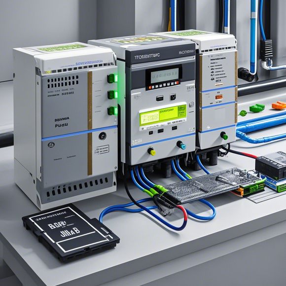
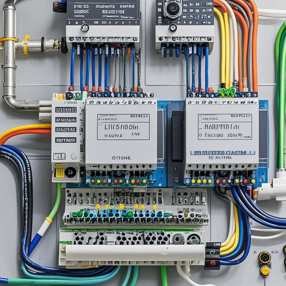
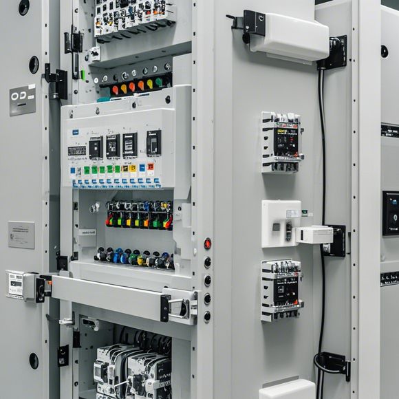
The first thing we see is a series of interconnected wires and components, which are all connected to each other via different connectors. Each component has a unique purpose, and their correct placement is essential for the smooth operation of the entire system. For example, the input/output (I/O) modules serve as the gateway between the external world and the PLC controller, allowing us to receive data from sensors or send commands to motors. The communication modules, on the other hand, facilitate the exchange of information between different devices within the network.
Now, let's move on to the programming aspect. The PLC controller is designed to be programmable, allowing us to customize its functionality based on specific requirements. This means that we need to have a clear understanding of the programming language and syntax used in our application. In this case, we are using a popular industrial standard, such as PROFIBUS or Modbus, which allows us to easily connect to various devices and perform complex operations.

One of the most important tasks when it comes to programming is to ensure that the connections between the components are correct. This involves testing the circuitry before and after each modification to make sure there are no errors or discrepancies. It's also crucial to follow the manufacturer's guidelines for programming the PLC controller, as some configurations may require additional settings or adjustments.
Another important aspect of the PLC controller system is the safety features. All electrical components must be designed to withstand high voltage and current levels, and there should be proper grounding and protection mechanisms in place to prevent damage during faulty conditions. Additionally, we must ensure that all cables and connectors meet the necessary electrical standards, such as those required by the National Electrical Code or International Electrotechnical Commission (IEC).

Finally, when it comes to maintaining and troubleshooting the PLC controller system, we need to have a solid knowledge base of common issues and solutions. This includes familiarity with common hardware and software problems, such as lost connections, corrupted data, or outdated firmware. We can also use specialized tools and diagnostic techniques to quickly identify and resolve these problems, ensuring that our PLC controller system remains reliable and functional.
In conclusion, as a professional in the international trade industry, it's crucial to have a thorough understanding of our PLC controller system's physical layout, programming logic, and safety features. By following the manufacturer's guidelines, testing connections properly, and staying up-to-date with best practices and updates, we can ensure that our PLC controller system is both reliable and efficient.

Content expansion reading:
Articles related to the knowledge points of this article:
Mastering the Art of Plc Controllers: A Comprehensive Guide to Understand and Implement
How to Use a PLC Controller for Your Business
PLC (Programmable Logic Controller) Control System Basics
Plumbers Rule! The Role of PLC Controllers in the World of Waterworks
The Role of Programmable Logic Controllers (PLCs) in Foreign Trade Operations