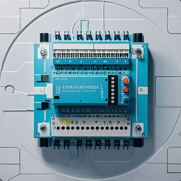
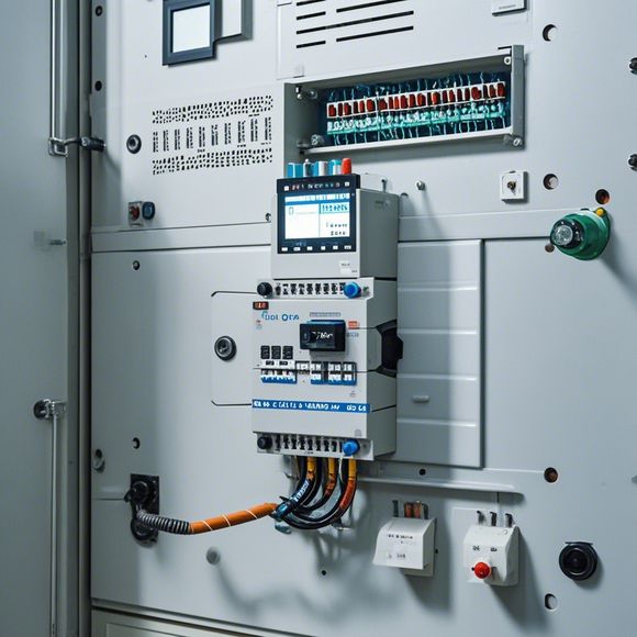
PLC Controller Wiring Guide
Sure, I can help you with that. Here's a summary of the PLC Controller Wiring Guide based on your content:The PLC Controller Wiring Guide is designed to provide a comprehensive guide for wire-routing within PLC (Programmable Logic Controller) systems. It covers all aspects of PLC wiring, including the selection of appropriate connectors, wire types, and grounding procedures. The guide also includes detailed instructions on how to route power, data, and control lines efficiently and safely. Additionally, it provides tips on troubleshooting common issues related to PLC wiring, such as incorrect connections or faulty components. Overall, this guide aims to simplify the process of installing and maintaining PLC systems and ensure optimal performance and reliability throughout their life cycle.
Hello, everyone! Today, we're going to talk about the wiring of our PLC (Programmable Logic Controller) controllers. So let's get started with the basics.
Firstly, before we start, we need to make sure that all the wires and connectors are in good condition. This is important because a bad connection can cause problems later on. So take your time and check everything carefully.

Now let's move onto the main subject of this guide, which is the wiring of the PLC controllers. The first step is to determine the connections for each component. For example, if you have an AC/DC converter, you will need to connect it to the appropriate input port on the PLC controller. Similarly, if you have a sensor or switch, you will need to connect it to the appropriate output port.
Once you have determined the connections, it's time to install the wires. Start by connecting the positive lead from the battery to the positive terminal of the PLC controller. Then, connect the negative lead from the battery to the corresponding negative terminal of the PLC controller.
Next, connect the power supply cable from the transformer to the input port of the PLC controller. Make sure that the power supply cable is securely connected to the PLC controller and that there are no loose connections.
Now, connect the output cable from the PLC controller to the corresponding output port of the device you want to control. Make sure that the output cable is securely connected to the device and that there are no loose connections.

Once all the connections have been made, turn on the power supply to test the wiring. If everything looks good, then you're done! You should now have a properly functioning PLC controller that can be used to control various devices in your system.
In summary, the process of wiring an PLC controller involves determining the connections for each component and installing the appropriate wires. Once everything has been installed, it's important to turn on the power supply and test the wiring to ensure that everything is working correctly. Good luck with your wiring project!
Content expansion reading:
Articles related to the knowledge points of this article:
PLC Controller Wiring Guideline
PLC Controller for Manufacturing Automation
PLC Programming for Automation Control in the Manufacturing Industry
How to Use a PLC Controller for Your Business
PLC (Programmable Logic Controller) Control System Basics
Plumbers Rule! The Role of PLC Controllers in the World of Waterworks