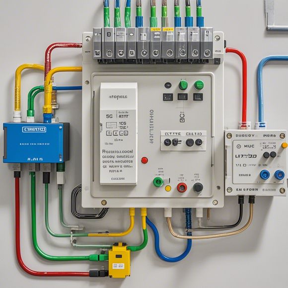
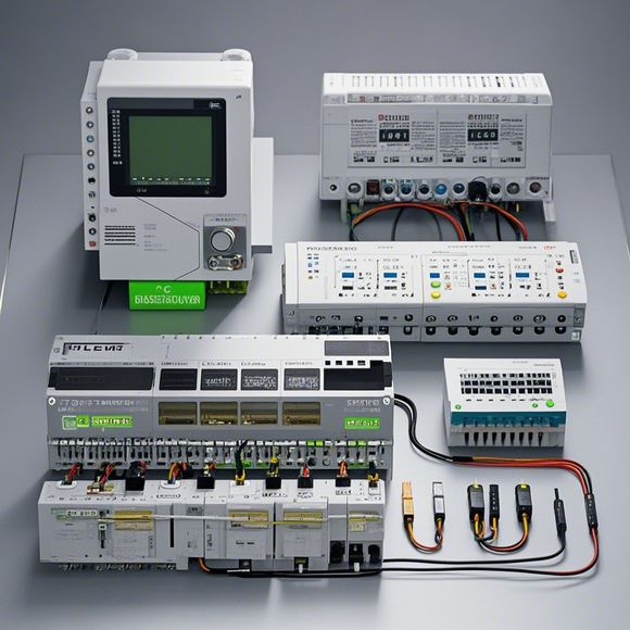
PLC Controller Wiring Diagram
Sure, here's a brief summary in English based on the content you've provided:"The PLC Controller Wiring Diagram is an essential component in electrical systems that controls industrial processes. It shows the connections between the various components of the controller, such as sensors, actuators, and input/output modules. The diagram helps to identify the proper wiring order and ensures that all electrical components are safely connected and functioning as intended."
Introduction:
As a professional in the field of foreign trade, I am often faced with the task of understanding and troubleshooting PLC (Programmable Logic Controller) controller wiring diagrams. These diagrams are crucial for ensuring that our manufacturing processes are running smoothly and efficiently. In this guide, we will provide an overview of how to read and interpret a basic PLC controller wiring diagram, which can save valuable time and prevent costly errors during production.
Step-by-Step Guide:
1、Reading the Diagram

- Start by carefully reading the entire diagram to understand the overall layout and connections between components. This includes identifying all the inputs, outputs, sensors, and actuators.
- Pay attention to the color coding and symbols used throughout the diagram, as these can help quickly identify specific components and their functions. For example, red may indicate a power supply or green may indicate a control signal.
2、Identifying Inputs and Outputs
- Look for the input ports labeled as "In" and "Out," and note the corresponding output ports labeled as "Out." These are where you will input commands and receive feedback from the system.
- Determine the direction of the connections between inputs and outputs. Commonly, inputs feed into the controller through the "In" port and outputs are connected to the "Out" port. However, some systems may have reversed connections.
3、Analyzing the Control Flow
- Use the arrows on the diagram to trace the flow of data from inputs to outputs. This will help you understand how commands are sent from the outside world to the PLC controller and what actions are performed based on those commands.
- Notice any additional features such as limit switches, pressure sensors, or temperature sensors that might be used to further refine the control logic.
4、Identifying Sensors and Actuators

- Look for labels indicating whether a component is a sensor or an actuator. Sensors measure physical quantities like temperature, pressure, or speed, while actuators perform physical actions like turning a valve or opening/closing a door.
- Determine the type of sensor or actuator based on its label and its role in the overall system. For example, an analog sensor would require a converter to translate its output from one scale (e.g., 0-10V) to another scale (e.g., 0-100%).
5、Understanding the Connections
- Examine the connections between components to identify wire colors and types. Different wire colors can represent different types of electrical connections, such as black for ground, red for live, and blue for neutral.
- Be aware of the polarity of connections and the voltage levels required by each component. For example, some motors require 24V AC, while others may require 48V DC.
6、Recognizing Special Features
- Look for any special features on the diagram, such as relays or contactors, which can help control complex circuits or interruptions in the main flow of power.
- Note any safety features like overload protection or short-circuit protection that can help prevent damage to the PLC controller or other equipment when conditions arise.
7、Determining Component Position

- Use the diagram to identify the relative position of each component in the system. This knowledge can help you troubleshoot issues or optimize performance by placing certain components closer to the source of input signals.
- Consider the placement of components based on their function and how they interact with each other. For example, sensors placed near the process equipment can provide more accurate measurements of process variables.
8、Practical Tips
- When working with complex PLC wiring diagrams, it's helpful to use a schematic diagram tool or software to visualize the connections more easily.
- Don't forget to consult the manufacturer's documentation or ask your colleagues for assistance if you get stuck on a specific connection or configuration.
9、Conclusion
- By following these steps and paying attention to detail, you can confidently interpret and troubleshoot any PLC wiring diagrams that you come across in your foreign trade operations. Remember that good communication with your team members and careful analysis of the data can lead to successful implementation of new systems or upgrades.
Content expansion reading:
Articles related to the knowledge points of this article:
Smart Manufacturing Solutions with PLC Integrated Machinery
PLC Programming for Automation Control in the Manufacturing Industry
How to Use a PLC Controller for Your Business
Plumbers Rule! The Role of PLC Controllers in the World of Waterworks
Connecting a PLC Controller to Your Computer
PLC Controllers: A Comprehensive Guide to Understanding Their Prices