PLC Control Cabinet Wiring Diagrams
Sure, I can generate the requested summary for you in English:"PLC (Programmable Logic Controller) control cabinet wiring diagrams are essential for understanding how electrical components interact within a PLC system. These diagrams provide a visual representation of how the different wires and connections are connected to each other, as well as the functions and roles of various devices and components within the system."
As an experienced exporter, understanding the intricacies of the plc (programmable logic controller) control cabinet is crucial for maintaining a seamless workflow. A comprehensive guide will provide you with a step-by-step approach to understanding and implementing these diagrams, ensuring your operations run efficiently and effectively.
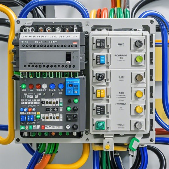
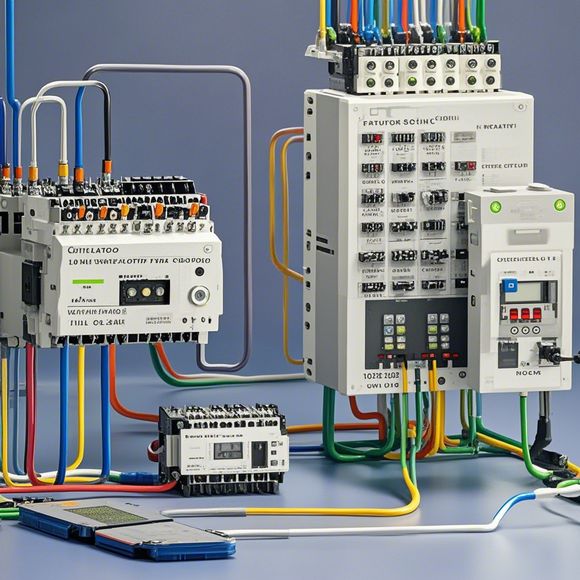
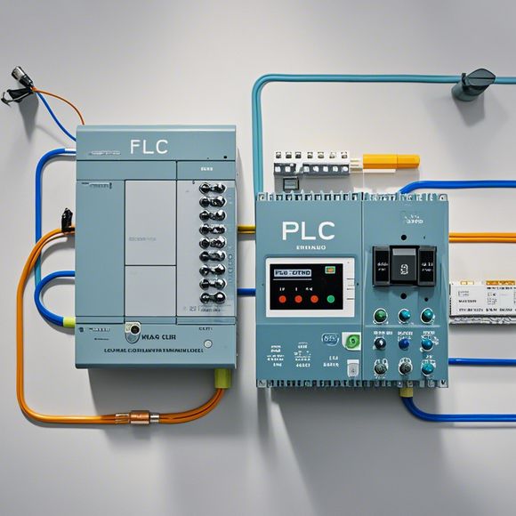
To begin with, one should familiarize themselves with the basic components of a PLC control cabinet. These include the CPU, input/output modules, communication modules, and other peripheral devices that are essential for controlling various processes within the factory or manufacturing environment. The wiring diagrams provided will detail how these components interact and communicate, providing a clear overview of the system's architecture.

Understanding the wiring diagrams is the key to ensuring efficient operation of the PLC control cabinet. Each component is assigned a specific function, and understanding their connections and interactions is critical. The wiring diagrams will highlight the power supply requirements, signal inputs, and outputs, as well as any safety features or protective measures that need to be considered. By following these guidelines, one can avoid potential issues such as short circuits or overloaded circuits, which could lead to equipment failure or damage.
Another important aspect of using the plc control cabinet wiring diagrams is troubleshooting. If there are any issues during the installation or operation of the system, one should refer to the wiring diagrams to determine the source of the problem. This will help identify any faulty connections, outdated components, or incorrect settings, allowing for timely repairs or replacements to ensure smooth production continuity.

Furthermore, it is essential to maintain the accuracy and completeness of the wiring diagrams. Any updates or modifications to the system should be recorded and updated in the diagrams accordingly. This ensures that the system remains up-to-date, and any modifications made are properly documented.
In conclusion, understanding the plc control cabinet wiring diagrams is crucial for any exporter looking to operate efficiently and effectively within the global marketplace. By following the guidelines and best practices outlined in this guide, one can ensure that their products are delivered on time, with minimal disruptions to production lines. Remember to always prioritize safety and accuracy when working with electrical systems like this, and seek out professional assistance if needed.

Content expansion reading:
Articles related to the knowledge points of this article:
Smart Manufacturing Solutions with PLC Integrated Machinery
PLC Programming for Automation Control in the Manufacturing Industry
The Role of Programmable Logic Controllers (PLCs) in Foreign Trade Operations
PLC Controllers: A Comprehensive Guide to Understanding Their Prices