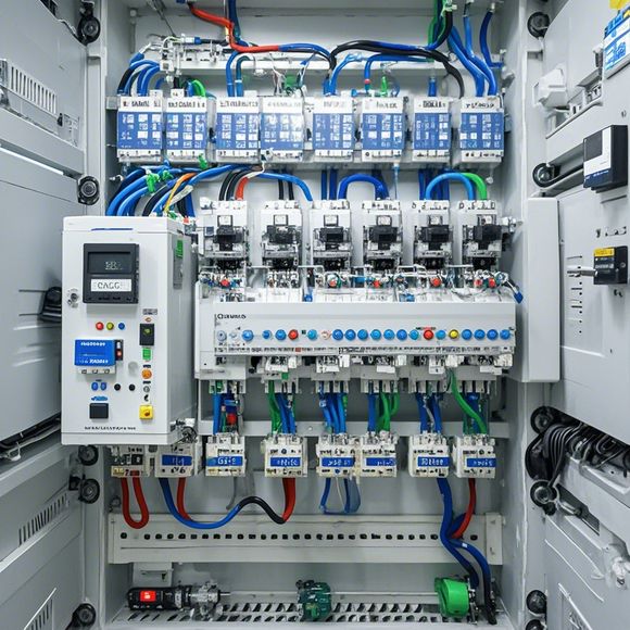
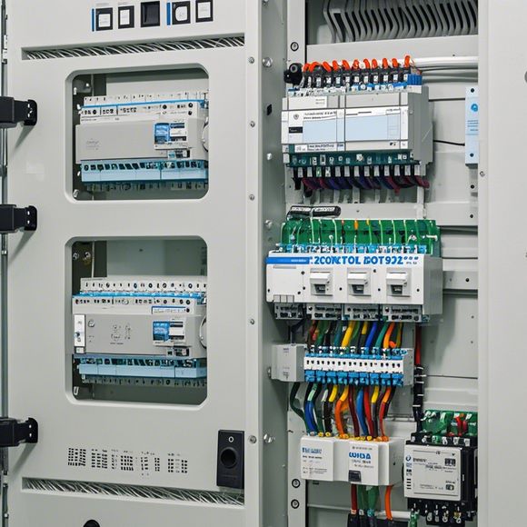
Introduction to the PLC (Programmable Logic Controller) Module Wiring Diagrams
Sure, here's a brief summary in English:The Programmable Logic Controller (PLC) module wiring diagrams are essential for understanding how the PLC communicates with other devices in a process control system. These diagrams typically include the connections between various components such as sensors, actuators, and processors.In a typical PLC module, there is an input section that receives data from sensors or other devices, and an output section to send commands to motors or other equipment. The wiring diagram shows the connections between these components and the PLC itself.By examining the wiring diagram, engineers can quickly identify any issues with the communication between components and troubleshoot problems before they occur. This is especially important in industrial settings where safety must be paramount and delays can have serious consequences.
Dear all,
Welcome to our discussion on the topic of Programmable Logic Controller (PLC). In today's digital age, understanding how to wire PLC modules is crucial for anyone working in the manufacturing and automation industry. Let's delve deeper into this fascinating world and explore the various components that make up a PLC system.
At its core, a PLC is a powerful tool that can automate complex industrial processes with ease. It operates by storing data in memory and processing it according to predefined instructions, which are stored in a variety of configurations known as programs. These programs control the flow of information between the input and output devices within the PLC system.

When it comes to wiring PLC modules, there are several key components that must be considered. Firstly, there are the power supplies, which provide electricity to the PLC modules. These power supplies are typically designed to handle high currents and voltages, making them reliable and safe for use in industrial environments.
Next up is the input/output modules, which are responsible for receiving and sending signals to and from external devices. These modules are designed to interface seamlessly with other systems, allowing for seamless communication between different components in the PLC network.
Now let's talk about some common wiring techniques used to connect PLC modules. One method is the use of cables known as ribbon cables or strip cables, which provide a secure and reliable connection between modules without the risk of loose connections or damage to the wires.
Another popular technique involves using connectors, such as screw-in connectors or push-in connectors, which simplify the wiring process and ensure a strong and stable link between modules.

In addition to connecting individual modules, it's also important to consider the overall layout of the PLC system. This includes factors like the placement of sensors, valves, and other critical components, as well as the selection of appropriate wiring harnesses and cable lengths. By carefully planning the design and installation of the PLC system, businesses can optimize their operations and improve efficiency.
One example of a typical PLC system is found in a manufacturing plant where a conveyor belt moves materials through a series of automated machines. Each machine has a corresponding PLC module, which controls the movement and operation of the machinery. The input/output modules receive signals from sensors that monitor the status of each machine, while output modules communicate with other systems such as conveyor belt controllers or assembly line operators.
The benefits of PLC systems are numerous, from improved accuracy and reliability to reduced downtime and increased productivity. When properly configured and maintained, they can help businesses streamline their operations and remain ahead of the competition.
However, it's important to note that while PLCs offer many advantages, they also come with certain limitations. For example, they may not be suitable for all applications or industries, as their complexity and cost may outweigh their benefits. Additionally, there may be concerns around security and privacy when dealing with sensitive data or information.

Despite these challenges, the future of PLC systems looks bright, as technology continues to advance at an unprecedented pace. With advancements in artificial intelligence and machine learning, PLC systems are expected to become even more powerful and flexible, enabling even more advanced automation solutions.
In conclusion, understanding how to wire PLC modules is essential for anyone working in the manufacturing and automation industry. By taking the time to learn about the various components that make up a PLC system and exploring some common wiring techniques, businesses can take advantage of these powerful tools and achieve greater success in their operations. So why wait? Let's get started today and start unleashing the full potential of PLC systems!
Content expansion reading:
Articles related to the knowledge points of this article:
PLC Controller for Manufacturing Automation
How to Use a PLC Controller for Your Business
PLC (Programmable Logic Controller) Control System Basics
The Role of Programmable Logic Controllers (PLCs) in Foreign Trade Operations
PLC Controllers: A Comprehensive Guide to Understanding Their Prices