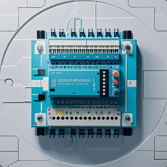
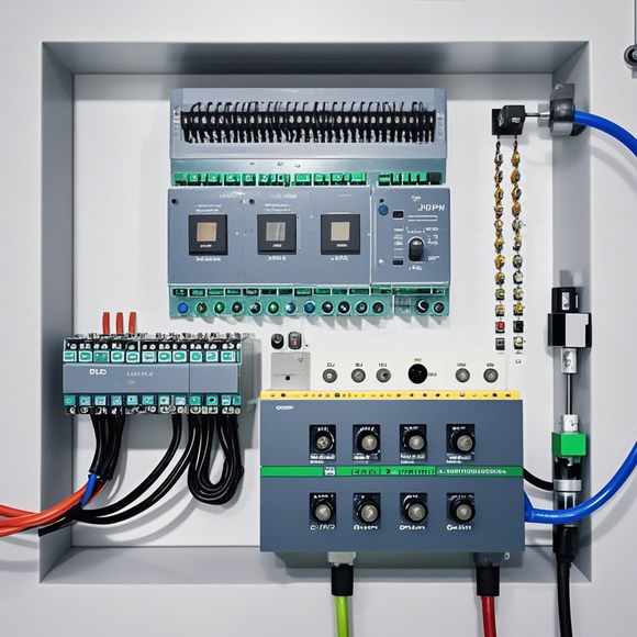
PLC Control Principle Diagram
Certainly, based on your content, here's an outline of a 200-300-word summary in spoken English:---**Summary: The Control Principle Diagram of Programmable Logic Controller (PLC)**In the world of industrial automation, Programmable Logic Controllers (PLCs) play a vital role. These devices are designed to automate processes and control systems, making them incredibly useful for industries that require precise control over their operations. The key to the successful operation of any PLC lies in its control principle diagram, which outlines the internal workings of the device and how it communicates with various components within the system.A typical PLC control principle diagram includes several key elements:1. **Input/Output Devices**: These are the interfaces between the PLC and the rest of the industrial process. They receive signals from various sensors and transmit data back to the PLC for processing.2. **Clock and Data Memory Unit (CDU)**: This is where the PLC stores information and performs calculations. It also provides a clock signal to ensure accurate timing of events.3. **Process Control System (PCS)**: The PCS is responsible for setting up the PLC to control specific functions of the industrial process. It allows the PLC to understand what needs to be achieved and how to achieve it.4. **Programming Interface**: This interface allows users to program the PLC with instructions for controlling the process. It can be either a hardware interface or a software interface, depending on the manufacturer's choice.5. **Communication Channels**: These channels allow the PLC to exchange information with other devices in the industrial system. They may include communication protocols like Ethernet or PROFIBUS.The control principle diagram is a crucial component for understanding how an PLC operates. By analyzing the diagram, you gain insight into how each part of the system interacts with each other to achieve the desired outcome. This knowledge is essential for maintaining efficient and effective industrial operations.
Introductory paragraph in English:
Hello, everyone! Today I'm excited to discuss the topic of PLC (Programmable Logic Controller) control principle diagram with you all. As a professional in the field of foreign trade operations, understanding how these devices work is crucial for managing and automating our processes. So, without further ado, let’s dive right into it!

Firstly, let's take a quick look at what a PLC control principle diagram is. It's essentially an electronic circuit that uses programming code to autonomously control various industrial processes. This means that instead of relying on human intervention, we can program these machines to perform specific tasks efficiently and accurately.
Now, let me give you an example of what a typical PLC control principle diagram looks like. Picture this: You have a factory where multiple machines are working simultaneously to produce goods. Each machine has its own individual control system, and the PLC is responsible for coordinating all of them. The PLC receives input signals from sensors, analyzes them, and then sends output signals to motor controllers, switches, or other devices to make the necessary adjustments.
So, imagine if each machine had its own little brain, and they were communicating with one another using PLCs. The PLCs would be acting as the intermediary, taking care of the communication between different components and ensuring everything runs smoothly.

But wait, there's more! In addition to controlling individual machines, PLCs can also monitor overall system performance and alert us when there are any issues. They can even learn from past experiences and adjust their settings accordingly to optimize performance and reduce downtime.
Now, back to our main point. When it comes to designing and implementing a PLC control principle diagram, there are several key steps involved. Firstly, we need to identify the various components of our system, including sensors, switches, actuators, motors, etc. Then, we need to determine which ones need to be controlled by the PLC, and how they will interact with each other. Next, we need to create a logic flowchart based on the requirements of our system. Finally, we need to write the programming code that will enable our PLC to execute the logic diagram correctly.
Of course, there are many factors to consider when designing a PLC control principle diagram. For example, we need to ensure that our diagram is scalable enough to accommodate future expansions. We also need to consider energy consumption and efficiency, as well as cost-effectiveness. And finally, we need to ensure that our diagram is easy to understand and maintain.

In conclusion, a PLC control principle diagram is an essential tool for anyone involved in the automation of industrial processes. By following the steps outlined above, we can create a reliable and efficient system that will help us streamline our operations and improve productivity. So, don't hesitate to get started on your own PLC control principle diagram today!
Content expansion reading:
Articles related to the knowledge points of this article:
PLC Controller Selection Guide for Foreign Trade Operations
PLC Controller Wiring Guideline
The cost of a PLC Controller: A Comprehensive Analysis
PLC Programming for Automation Control in the Manufacturing Industry
Plumbers Rule! The Role of PLC Controllers in the World of Waterworks