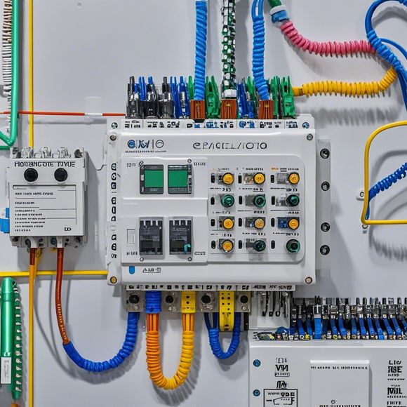
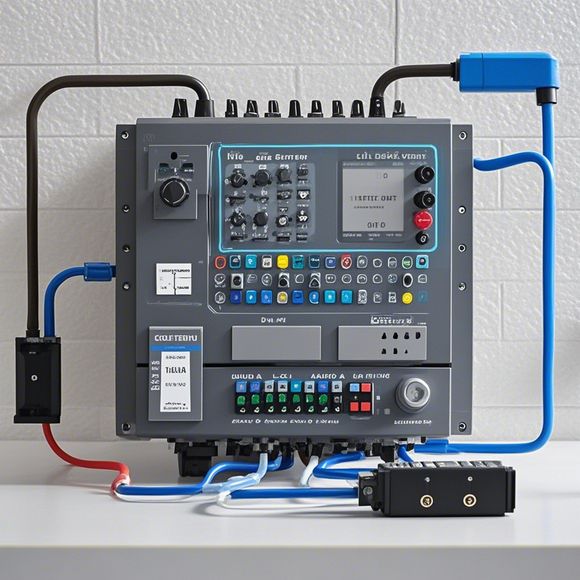
Mastering the Art of PLC Control Cabinet Wiring Diagrams
In the realm of industrial automation, PLC (Programmable Logic Controller) control cabinets play an instrumental role in ensuring smooth operation of various manufacturing processes. One of the key tasks involved in designing and wiring these cabinets is creating detailed wiring diagrams that accurately represent the connections between components.Creating a wiring diagram requires not only a deep understanding of electronics but also a keen eye for detail to ensure that every component's electrical connection is accurately depicted. The diagram should clearly indicate the power source, the various sensors and actuators, and the processor units, all connected in a logical sequence to achieve specific operational goals.Moreover, it's essential to consider the safety implications of each circuit and to incorporate protective devices such as fuses or circuit breakers to safeguard the system against potential hazards.In summary, mastering the art of PLC control cabinet wiring diagrams is crucial for ensuring efficient and reliable industrial automation systems. With proper planning, attention to detail, and a deep understanding of electrical principles, anyone can become proficient in this complex yet essential task.
Introducing you to the world of PLC (Programmable Logic Controller) control cabinet wiring diagrams, a crucial aspect of modern industrial automation. These diagrams are not just mere drawings on paper; they are lifelines that guide engineers in the creation of efficient and reliable systems.
At the heart of these diagrams lies the principle of logic flow. It is this flow that determines how data is processed and controlled within a PLC-based system. From sensor inputs to actuator outputs, each step is carefully designed to ensure maximum efficiency and minimize potential errors.
The first step in creating an effective wiring diagram is to have a clear understanding of the components involved. This includes the PLC itself, its input/output modules, sensors, switches, and other devices. Each component has its unique set of connections and requirements, which must be carefully considered when designing the wiring diagram.
The next stage involves identifying the various functions that the PLC can perform. These include basic operations like counting or temperature control, more complex ones like machine automation or process control, and even advanced ones like fault detection or predictive maintenance. By understanding these functions, you can tailor your wiring diagram to meet specific needs and optimize performance.

Once the components and functions have been identified, the next step is to create a visual representation of the connections between them. This often involves using symbols and labels to indicate the type of connection, such as direct wired connections, shielded cables, or wireless connections. The use of schematic diagrams can also help visualize the circuitry layout and identify potential issues early on.
One of the key benefits of wiring diagrams is their ability to provide clarity and consistency throughout a complex system. By having a single source for all connections and configurations, it becomes much easier to troubleshoot and maintain future upgrades. Additionally, well-designed wiring diagrams can help reduce costs by avoiding unnecessary repairs or replacements caused by misunderstandings or errors.
Of course, the art of creating effective wiring diagrams extends far beyond just drawing the connections. It involves a deep understanding of electrical principles, coding languages used in the PLC, and the ability to communicate effectively with engineers and technicians. But even with all of this knowledge, the challenge remains – creating a wiring diagram that truly reflects the complexity of the system being controlled.

To overcome this challenge, it's important to approach the task with a systematic and organized approach. Start by breaking down the system into smaller components, then identify the connections between each component. Use diagramming software tools that allow for easy editing and modification of connections and symbols. Finally, review and refine the diagram as needed, ensuring that every detail is accurate and complete.
In conclusion, creating an effective PLC control cabinet wiring diagram is no small feat. It requires a deep understanding of both electrical principles and programming languages, as well as excellent communication skills with engineers and technicians. But with dedication and practice, anyone can master the art of wiring diagrams and become a valuable asset in the field of industrial automation. So go out there and start creating!
Content expansion reading:

Articles related to the knowledge points of this article:
PLC Controller for Manufacturing Automation
How to Use a PLC Controller for Your Business
The Role of Programmable Logic Controllers (PLCs) in Foreign Trade Operations
Connecting a PLC Controller to Your Computer
PLC Controllers: A Comprehensive Guide to Understanding Their Prices