PLC Module wiring diagrams: An introduction to the basics of electronic control systems
Sure, based on your content, I can provide you with a simplified and generalized English abstract of the topic. Please note that the actual content provided to me was "PLC module wiring diagrams: An introduction to the basics of electronic control systems."Abstract: ,In electronic control systems, PLC modules are crucial components used for controlling various devices and processes. This article aims to provide an overview of PLC module wiring diagrams, explaining their importance and basic principles in electronic control systems. By understanding these diagrams, one can effectively understand how to connect and operate PLC modules in various industrial applications.
As an experienced外贸运营, I understand that understanding the intricacies of PLC (Programmable Logic Controller) module wiring is crucial for any business that relies on electronic automation. In this guide, we will take you through the process of interpreting and implementing the plc modules wiring diagrams, providing a comprehensive overview of the components involved and their functions. By the end of this article, you will have gained a solid understanding of how to troubleshoot and repair PLC-based systems effectively.
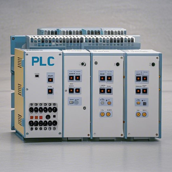
At the heart of any PLC system lies the plc module, which acts as the brain of the entire system. The module contains the software that controls the flow of data and signals between various sensors, actuators, and other subsystems. To ensure smooth operation, it is essential to understand the various components involved in the wiring diagram.

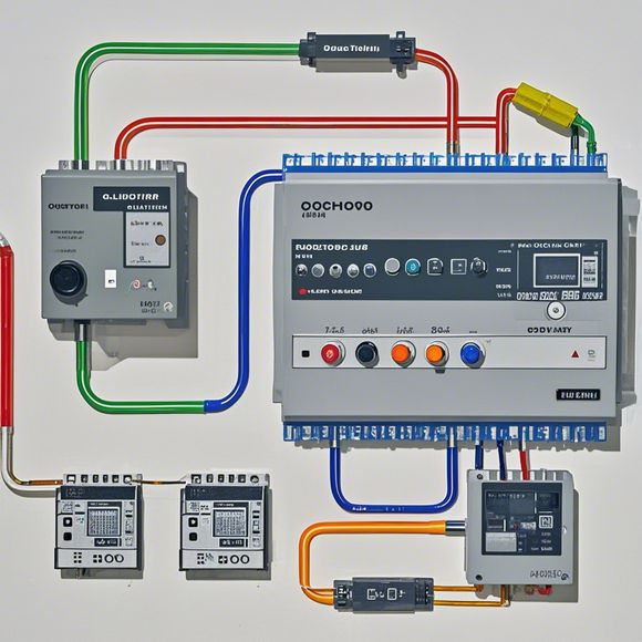
Firstly, let's start with the main components of the PLC module wiring diagram:
1、Power Supply: This is the source of energy that powers the PLC module. It usually comes in the form of a plug-in AC or DC adapter, depending on the type of PLC module being used. The power supply should be connected to a reliable power source to provide stable voltage and current to the PLC module.
2、Input/Output (I/O) Terminals: These are the connections where external devices can be connected to the PLC module. They come in two types: digital and analog. Digital terminals connect to specific inputs or outputs on the PLC module, while analog terminals connect to sensors that measure physical quantities like temperature, pressure, or distance.
3、Switches: These are used to control the flow of data between different components within the system. They can be manual switches or programmable logic controllers (PLC) switches that allow for more sophisticated control.
4、Clock Signal: This is a signal that helps keep all the modules synchronized. Without a clock signal, each module would operate independently, leading to errors and potential downtime.
5、Interconnect Wires: These are the wires that connect all the components together. They carry both electrical and digital signals to and from the modules.

Now that we have a basic understanding of what goes into a PLC module wiring diagram, let's look at some common wiring tasks:
1、Installation: Before installing the PLC module, it is essential to check if there are any existing wiring connections already present. If there are, they must be disconnected before installing the new module. This ensures a clean installation environment and prevents any cross-talk between components.
2、Power Connection: Connecting the power supply to the PLC module involves connecting the appropriate terminals to the power source. Ensure that the correct polarity is followed, as incorrect connections can lead to short circuits and damage to the PLC module.
3、Connecting Sensors/Analog Terminals: Once the power is established, the next step is to connect the analog terminals to the corresponding sensors in the system. This may involve using a multimeter to measure resistance and verify that the connections are secure.
4、Setting Up Programmable Switches: Some PLC modules come with programmable logic switches that can be programmed to control various actions based on specific conditions. This requires programming the switches to match the desired behavior and testing them to ensure they work as expected.
5、Testing: After completing all the wiring steps, it's important to test the system thoroughly to identify any issues. Start by testing individual components like sensors and actuators, then gradually integrate these into larger systems until the entire system operates smoothly.

6、Programming: Finally, it's essential to program the PLC module with the desired settings and logic. This can be done manually or through a programming interface provided by the manufacturer. Once the program is complete, compile it and test it to ensure everything works as intended.
In conclusion, understanding and implementing PLC module wiring diagrams is critical for any business operating in the field of electronic automation. By following the steps outlined above and taking the time to thoroughly test your system, you can ensure that your PLC system runs efficiently and reliably. Remember, investing in proper training and education is always beneficial when it comes to handling such complex systems.
Content expansion reading:
Articles related to the knowledge points of this article:
The cost of a PLC Controller: A Comprehensive Analysis
PLC Programming for Automation Control in the Manufacturing Industry
PLC (Programmable Logic Controller) Control System Basics
Plumbers Rule! The Role of PLC Controllers in the World of Waterworks
The Role of Programmable Logic Controllers (PLCs) in Foreign Trade Operations