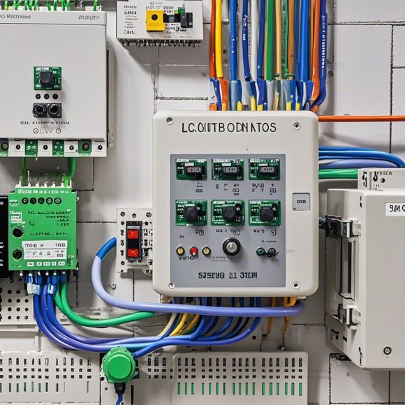
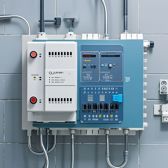
PLC (Programmable Logic Controller) Input/Output Interface Diagram
Sure! Here's a summary of what you provided in simplified terms:PLC (Programmable Logic Controller) is a device used for controlling various industrial processes and systems. It can handle a large number of inputs and outputs, allowing it to interact with different devices and sensors. The I/O interface diagram is an essential component that shows the connections between different components of the PLC system.In this diagram, there are various types of connections such as digital and analog signals. Digital signals include pulse width modulated signals, which are commonly used in control systems, while analog signals represent values ranging from -10 V to +10 V.The diagram also shows the different types of sensors used in the system. Some common sensors include temperature sensors, pressure sensors, and flow sensors among others. These sensors help monitor different parameters in real-time to ensure the system operates efficiently.Overall, understanding the PLC I/O interface diagram is crucial for ensuring smooth operation of the industrial process. It provides insights into how different inputs and outputs are connected and how they contribute to the overall system's functionality.
Dear friends and partners,

I hope this message finds you all in great spirits. As a seasoned professional in the field of foreign trade operations, it is my privilege to introduce you to the intricate world of programmable logic controllers (PLCs), which play a crucial role in managing and controlling industrial processes on a global scale. Today, I will delve into the fascinating world of PLC input/output interface diagrams, providing insights into their design, function, and application.
At its core, a PLC is an automated control system that can be programmed to perform specific tasks based on predefined instructions. These instructions are stored in memory and executed by the PLC's microprocessor, which executes the program code stored in the PLC's memory. The PLC inputs and outputs are essential components that enable real-time monitoring and control of various industrial processes.
Let us start with the PLC input section. An input section refers to the signals or data that are fed into the PLC for processing. In the context of manufacturing industries, these inputs may include temperature sensors, pressure gauges, motion sensors, or even human input, depending on the specific process being controlled. The purpose of the input section is to provide accurate and reliable data to the PLC for decision-making and execution of tasks.
The PLC output section, on the other hand, refers to the signals or data that are sent out from the PLC to control physical devices such as motors, valves, lights, or alarm systems. The output signals are designed to drive the desired action within the plant, ensuring that production processes run smoothly and safely.
When it comes to designing an input/output interface diagram, several critical elements must be considered:
1、Functionality: The first step is to identify the functions required by the PLC input/output sections. This involves understanding the specific tasks that need to be performed and determining how they relate to each other. For instance, if one part of the factory requires temperature control, then the PLC input section would need to include temperature sensors and the corresponding output section would control heating or cooling systems accordingly.
2、Data Transmission: Once the functional requirements are established, the next step is to determine how the data will be transmitted between different parts of the plant. This involves considering factors such as distance, speed, and accuracy. For example, if the PLC is located in a remote area of a factory, then wireless communication technology like Wi-Fi or Bluetooth would be employed to transfer data.

3、Efficiency: It is also important to consider the efficiency of data transmission. For instance, using high-speed communication protocols such as Ethernet or PROFINET can ensure quick data transfer without compromising on reliability or security. Additionally, redundancy measures such as multiple cables or backup power sources should be implemented to prevent downtime due to faulty connections or equipment failures.
4、Reliability: Reliability is critical when designing an input/output interface diagram. Ensuring that the system can maintain its functionality even in adverse conditions such as power outages or hardware failures is paramount. This can be achieved by implementing robust error detection and correction mechanisms, as well as incorporating redundant components and backup systems.
5、Scalability: Finally, it is important to consider future scalability when designing an input/output interface diagram. This involves designing the system with flexibility and adaptability in mind, allowing for easy expansion or modification as the plant grows or changes over time. For example, using modular components or pluggable hardware can facilitate easier integration and upgrades in the future.
In conclusion, designing an input/output interface diagram for a PLC is a complex but vital task that requires careful consideration of functional requirements, data transmission methods, efficiency, reliability, and scalability. By following the steps outlined above and considering all these factors, businesses can ensure that their PLC systems operate efficiently and effectively, ultimately driving productivity and profitability in their industrial operations.
Content expansion reading:
Articles related to the knowledge points of this article:
The cost of a PLC Controller: A Comprehensive Analysis
PLC Programming for Automation Control in the Manufacturing Industry
How to Use a PLC Controller for Your Business
Plumbers Rule! The Role of PLC Controllers in the World of Waterworks
The Role of Programmable Logic Controllers (PLCs) in Foreign Trade Operations
PLC Controllers: A Comprehensive Guide to Understanding Their Prices