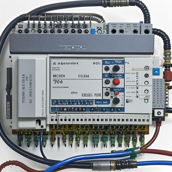
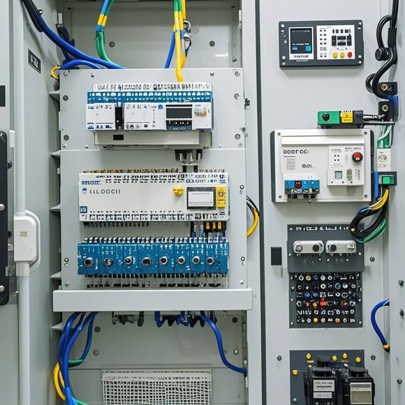
PLC Controller Wiring Diagram: A Guide to Mastering the Art of Automation
Sure, I can help you with that. Here's a concise summary of the PLC Controller Wiring Diagram:This guide is designed to help you master the art of automation by providing a comprehensive understanding of the PLC controller wiring diagram. It includes information on the different types of wire connections, the importance of grounding, and the proper placement of components in the circuit. Additionally, it covers common issues and solutions, such as faulty wiring or improper component placement. By following these guidelines, you can ensure that your automation system is safe, reliable, and efficient.
Dear colleagues,
As we delve into the world of manufacturing, one aspect that cannot be overlooked is the intricate interplay between different systems. Amongst these systems, the Programmable Logic Controller (PLC) stands out as a cornerstone of automation in various industries. Its ability to control complex processes and automate industrial tasks has made it a crucial component in modern factories. However, the task of wiring up an PLC controller demands precision and expertise. In this guide, I'll take you through the essential steps involved in creating a functional PLC controller wiring diagram.

Firstly, let’s start by understanding what an PLC controller is. An PLC controller is a device that performs calculations and controls based on predefined logic programs written in a specific programming language. It operates independently of human intervention, making it ideal for tasks that require high levels of accuracy and efficiency. Whether it be in manufacturing, healthcare, or any other industry sector, an PLC controller can help streamline operations and improve productivity.
Now, onto the topic at hand—the creation of a PLC controller wiring diagram. This document serves as a roadmap for assembling all the electronic components required to interface with your PLC. Here are some key steps to follow:
1、Identify the Components: The first step in creating a wiring diagram is to list all the components you will need. These include sensors, actuators, switches, relays, power supplies, and other devices that may be connected to your PLC. Once you have a complete list, you can begin to visualize how they will be connected.
2、Determine the Power Source: Next, determine the type of power source that will be used to power your PLC. Will it be AC or DC? And if so, what voltage range? This information will help you choose the appropriate power supply unit (PSU) and connectors needed for each component.
3、Assess Sensor and Actuator Requirements: Now, consider the types of sensors and actuators that will be used in your system. Do you need temperature sensors? Pressure sensors? If so, identify their respective connections and ensure they are properly routed to the PLC input/output ports.

4、Connect Power Lines: Connect the power lines from your PSU to the appropriate terminals on the circuit board or enclosure of your PLC. Ensure all cables are securely attached and labeled for easy identification.
5、Route Wires Properly: When connecting wires, follow the manufacturer's guidelines for proper routing. Avoid twisting or bending wires excessively as this can create electrical interference and damage the wiring.
6、Connect Sensors and Actuators: After ensuring the wires are routed correctly, connect your sensors and actuators to the appropriate inputs on the PLC. Use appropriate jumper wires or connectors to make sure everything is securely connected.
7、Test the Wiring: Once all connections are completed, test the entire system to ensure there are no short circuits or faulty connections. Check that all sensors and actuators are functioning properly and that the PLC is communicating with them correctly.
8、Documentation: Finally, make sure to document all connections and configurations clearly on the wiring diagram. This documentation can serve as a reference for future maintenance or upgrades. It should include details such as the type of sensor or actuator used, its specifications, and its connection to the PLC.

In conclusion, creating a functional PLC controller wiring diagram requires careful planning and attention to detail. By following these steps and taking note of important considerations like power sources and sensor/actuator requirements, you can confidently design and implement an efficient and reliable automated system. Remember, good communication between engineers and technicians is key to ensuring that your PLC controller is working smoothly and efficiently for years to come.
Content expansion reading:
Articles related to the knowledge points of this article:
PLC Controller Selection Guide for Foreign Trade Operations
PLC Controller for Manufacturing Automation
The cost of a PLC Controller: A Comprehensive Analysis
PLC Programming for Automation Control in the Manufacturing Industry
How to Use a PLC Controller for Your Business
The Role of Programmable Logic Controllers (PLCs) in Foreign Trade Operations