PLC Control Cabinet Wiring Diagram Explained
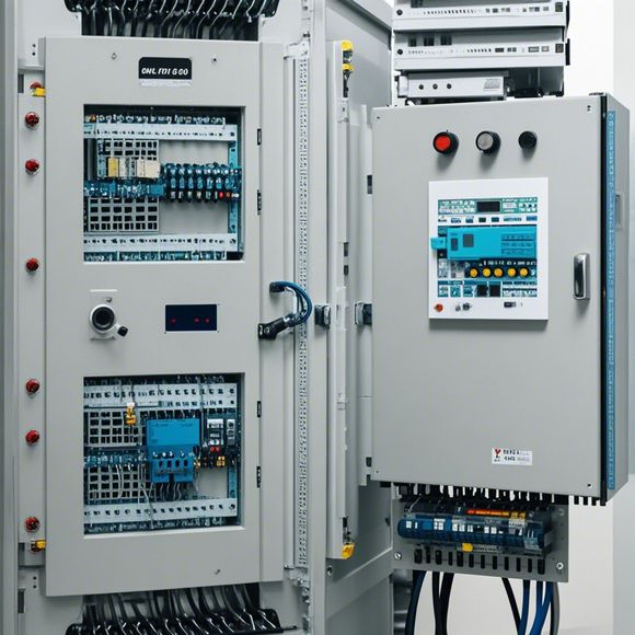
Sure, here is a summary in English for your PLC Control Cabinet wiring diagram:The PLC (Programmable Logic Controller) Control Cabinet is a crucial component in the automation system. It's responsible for managing and controlling different industrial processes. The wiring diagram of the Control Cabinet shows the connections between various components such as sensors, actuators, and control modules. This diagram allows engineers to understand the electrical circuitry and ensure that the PLC can communicate with all the devices connected to it. It also guides technicians on how to install and connect the cabling properly. Overall, understanding the wiring diagram is essential for maintaining the stability and reliability of the PLC Control Cabinet.
Introducing the world of automation, where precision and efficiency rule the roost! In this digital age that is reminiscent of an era gone by, we delve into the realms of PLC (Programmable Logic Controller) control cabinets. These marvelous machines are not just mere gadgets but masterpieces of engineering that have revolutionized the way industries function from the smallest scale to the grandest structures. Let's dive into the intricate wiring diagrams that make these marvels tick, tock, and hum with life.
Imagine, if you will, a scene where the very fabric of your business is intertwined with the pulse of technology. A control cabinet, a beacon of reliability in every corner of the world, is the backbone of your operations. It's the heart of the operation - a complex network of wires that communicates with sensors, actuators, and other devices, creating a seamless dance of information flow.
Now, let's take a closer look at the plc control cabinet's electrical system. It's like a puzzle with a thousand pieces, each one carefully placed to create a cohesive whole. The first layer of the puzzle is the power supply, which is often provided by a generator or battery pack, depending on the size and energy needs of your facility. This provides the foundational strength that fuels the entire system.
Next comes the primary power switch, which is often located near the main entrance of the control cabinet. This is the starting point for all electricity flow, turning it on or off as needed to ensure smooth operation. It's like the starting pistol, ready to fire the engine that powers your entire system.

Then there's the secondary power switch, which is usually located in a more accessible location, such as a utility closet or a separate room. This switch serves as an extra safeguard, providing an additional layer of protection against power surges or other unforeseen events. It's like the backup car in an emergency, always ready to roll when the main vehicle needs a rest.
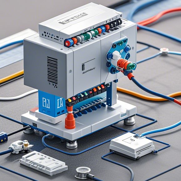
The next layer of the puzzle is the input/output modules, which are essentially the brain of the control cabinet. They receive commands from various sources, process them, and send out signals to the various devices within your facility. They work like neurons, transmitting information from one part of the system to another, ensuring that everything runs smoothly.
The output modules, on the other hand, are the motors, sensors, lights, and other devices that respond to the commands sent by the input modules. They're like muscle, flexibly responding to changes in the environment, ensuring that your systems remain responsive and efficient.
Now, let's talk about the communication between these components, which is what makes the control cabinet tick and tock. It's akin to a relay station, where signals travel across wires, passing through different stages before reaching their destination. This communication network is designed to be robust and reliable, ensuring that no message is lost or misinterpreted.
One of the most critical components of this network is the microcontroller, which is often referred to as the "brains behind the curtain." It acts as the controller, processing data from input modules and sending out commands to output modules. It's like the CEO of your company, making strategic decisions that affect the entire enterprise.

Another vital component is the program code, which is written in a specific language that allows the microcontroller to understand and execute its instructions. It's like the blueprint of your building, detailing how each component should interact with each other. Without it, your control cabinet would be a dead weight without a purpose.
Finally, we have the safety features, which are designed to protect your investment in case of any unexpected event. This could be overheating, short circuits, or any other fault. The safety features serve as a shield, protecting your equipment from harm and ensuring that your operations continue uninterrupted.
So there you have it, a glimpse into the inner workings of the PLC control cabinet. From the power supply to the safety measures, every aspect plays a crucial role in ensuring your business runs smoothly and efficiently. As you delve deeper into this fascinating world, don't forget that it's not just about hardware; it's also about understanding the software that controls it all. With the right combination of both, you can achieve unparalleled success in your industry.
Content expansion reading:
Articles related to the knowledge points of this article:
PLC Controller Wiring Guideline
PLC Programming for Automation Control in the Manufacturing Industry
How to Use a PLC Controller for Your Business
PLC (Programmable Logic Controller) Control System Basics
The Role of Programmable Logic Controllers (PLCs) in Foreign Trade Operations