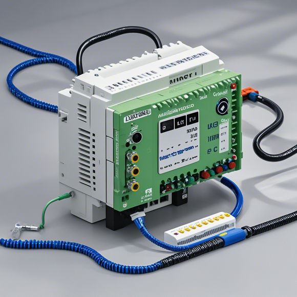
PLC Controller Cabinet Wiring Diagrams
Sure, here is a brief summary of what you provided in English:"PLC (Programmable Logic Controller) controller cabinet wiring diagrams are essential for understanding how the various components of the system are connected. The diagrams show the connections between the input and output modules, sensors, actuators, and other devices. These diagrams help in troubleshooting issues and diagnosing faults in the system. They provide a clear overview of the circuitry and its function, allowing technicians to quickly diagnose problems and make necessary adjustments."
As an experienced foreign trade operation, you may be tasked with understanding and interpreting the plc (programmable logic controller) controller cabinet's wiring diagrams. These wiring diagrams are critical in ensuring that the control system functions properly and securely according to the manufacturer's specifications. In this guide, we will discuss the key elements of a plc controller cabinet wiring diagram, including the main components and their connections.
Firstly, let's understand what a plc controller cabinet is. It is a device used to interface with various hardware components such as sensors, motors, and actuators, all controlled by a programmable logic controller. The cabinet contains the circuit boards, power supplies, and other components required to operate the system.
Next, let's examine the essential components of a plc controller cabinet's wiring diagram. These components include the following:

1、Power Modules: These modules provide the necessary electrical power for the control system. They convert alternating current (AC) into direct current (DC) for the circuits on the cabinet.
2、Circuit Boards: These boards house the electronic components that control the various operations of the system. Each board has its own set of connections, which must be accurately wired to ensure proper functionality.
3、Sensors: These are devices that detect physical changes or conditions and send data to the controller. For example, temperature sensors can detect changes in temperature and send the corresponding data to the controller.
4、Actuators: These are devices that perform mechanical actions based on signals from the controller. For example, a valve could be controlled by an actuator that opens or closes based on the output from the controller.
5、Input/Output Devices: These devices receive data from external sources such as keyboards, touchscreens, or barcode scanners, and provide output to external devices such as LED displays or printers.

Now that we have identified the main components of a plc controller cabinet's wiring diagram, let's discuss how they connect to each other.
The power modules supply the necessary voltage and current for the circuit boards, which contain the microcontroller and other digital circuitry. This allows the processor to execute instructions and communicate with other components.
The circuit boards are divided into several sections, each responsible for controlling different components of the system. For instance, one section might control sensors, while another section controls actuators.
Sensors collect data on various parameters and send it to the control system. The controller then processes this data and sends commands to the actuators to perform the desired actions.
Actuators respond to the commands from the controller and perform the actions specified by the software. For example, if a sensor detects a temperature change, the controller sends a signal to the actuator, which opens or closes the valve to regulate the flow of fluid to the heat exchanger.

Input/output devices allow users to interact with the system. For example, a user can input commands through a keyboard or touchscreen and see immediate feedback on LED displays or printed output.
In conclusion, the wiring diagram for a plc controller cabinet is critical in determining how the system operates. By understanding the connections between various components, you can ensure that the system functions properly and securely according to the manufacturer's specifications. If you have any questions or need further assistance, please feel free to ask!
Content expansion reading:
Articles related to the knowledge points of this article:
Smart Manufacturing Solutions with PLC Integrated Machinery
Plumbers Rule! The Role of PLC Controllers in the World of Waterworks
The Role of Programmable Logic Controllers (PLCs) in Foreign Trade Operations
PLC Controllers: A Comprehensive Guide to Understanding Their Prices