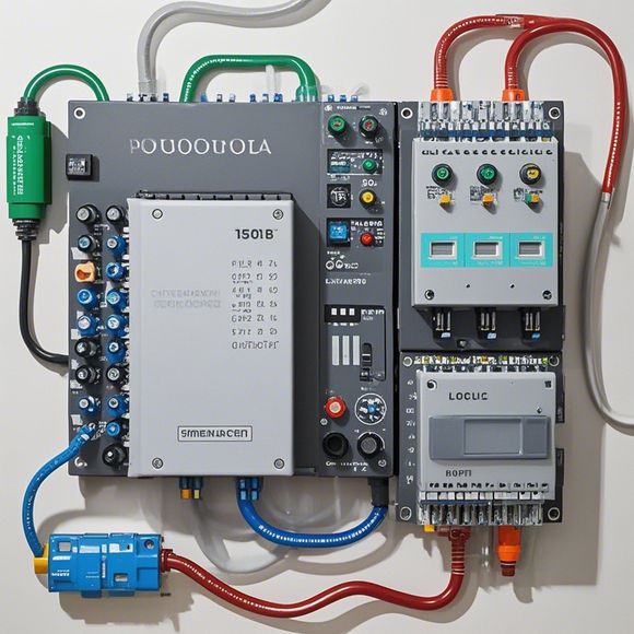
PLC Controller Wiring Guide
The PLC Controller Wiring Guide is a comprehensive document that provides step-by-step instructions for connecting wires in a PLC (Programmable Logic Controller). The guide covers various aspects such as the correct placement of wires, the selection of appropriate connectors, and the installation of terminal blocks. It also includes information on the types of wires used in different applications and their respective voltage ratings. Additionally, the guide provides safety tips and guidelines to ensure that wiring is done safely and efficiently. Overall, the PLC Controller Wiring Guide is a valuable resource for anyone who needs to understand how to properly connect wires in a PLC system.
Introduction:
Hello everyone, today we are going to discuss the process of wiring a PLC (Programmable Logic Controller) in your factory. A PLC is an essential tool in manufacturing industries, allowing for the automation of processes and reducing errors. By following the correct steps, you'll be able to ensure that your system is running smoothly. So let's begin!

Step 1: Gather the necessary materials
Before starting any work, make sure you have all the necessary equipment and tools. You will need a power supply, a screwdriver set, wire strippers, wire connectors, and a multimeter. Also, don't forget to gather the PLC controller and its wiring diagram.
Step 2: Disconnect the existing wiring
First, disconnect the existing wiring from the PLC controller. This will help you identify any faults and prevent any damage during the installation process. Use the screwdriver set to loosen the screws and remove the cover plate. Then, use the wire strippers to cut off the ends of the wires.
Step 3: Measure the length of the wire
Before you start connecting the wires, measure the length of the wires you need. This will help you avoid any unnecessary cuts or bends. Use the multimeter to check the resistance of each wire to ensure they are suitable for your circuit.
Step 4: Connect the wires to the PLC controller
Now, connect the wires to the PLC controller according to the wiring diagram. Start with the positive and negative leads, then proceed with the ground wire. Use the wire connectors and wire strippers to create a secure connection. Make sure to follow the instructions on the wiring diagram and avoid shorting out any components.
Step 5: Test the connection

After completing all the connections, test the connection by turning on the PLC controller. Use a multimeter to check the voltage levels and current flow. If everything seems fine, proceed with the next step. If there are any issues, take a break and try again later.
Step 6: Connect the sensors and actuators
Now it's time to connect the sensors and actuators to the PLC controller. Follow the manufacturer's instructions carefully, as not all sensors and actuators can be connected to the same type of PLC. Use the appropriate connectors and wires, and make sure to label them clearly for reference.
Step 7: Program the PLC controller
Finally, program the PLC controller according to the manufacturer's instructions. This may involve downloading the firmware, configuring settings, and programming routines. Once the program is ready, test it thoroughly before putting it into operation.
Conclusion:
In conclusion, wiring a PLC controller requires careful planning, precision, and attention to detail. Follow the steps outlined in this guide carefully and consult the manufacturer's documentation if needed. With proper wiring and programming, your factory can become more efficient, cost-effective, and reliable. Happy coding!
Content expansion reading:
Articles related to the knowledge points of this article:
How to Use a PLC Controller for Your Business
PLC (Programmable Logic Controller) Control System Basics
Plumbers Rule! The Role of PLC Controllers in the World of Waterworks
The Role of Programmable Logic Controllers (PLCs) in Foreign Trade Operations